What is a Series Circuit?
The complete guide to series circuits — components joined end-to-end on a single path. Learn why the current is the same everywhere, how the voltage divides (V = V1+V2+V3), why resistances add up, the voltage divider, and why one break stops the whole circuit.
Complete Learning Path — Series Circuits
From the single-loop idea and the three rules, to Ohm's law, the voltage divider, series vs parallel and real uses
What is a Series Circuit?
A series circuit is a circuit in which the components are connected one after another, forming a single, unbroken loop for the current. There is only one path, so the same current must pass through every component in turn.
Picture a single lane road with no junctions: every car (charge) that leaves the battery must travel through R1, then R2, then R3, and back — there is nowhere else to go. This one simple fact leads to the three rules of series circuits that the rest of this page unpacks.
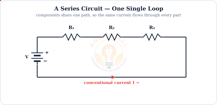
The three rules in one glance
Current: same through all — I = I1 = I2 = I3. Voltage: divides — V = V1 + V2 + V3. Resistance: adds — Rtotal = R1 + R2 + R3.
Rule 1: The Current Is the Same Everywhere
With only one path, charge cannot pile up or disappear — so exactly the same current flows through every component. Put an ammeter anywhere in the loop and it reads the same value.
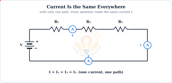
I = I1 = I2 = I3 = … = In
One current flows through every component of a series circuit
A common misconception
Current is not “used up” as it passes through resistors. The same current leaves the last resistor as entered the first — what changes along the way is the voltage, not the current.
Rule 2: The Voltage Divides (Kirchhoff's Voltage Law)
The supply voltage is shared out across the components. Each resistor takes a voltage drop, and all the drops add back up to the source. This is Kirchhoff's Voltage Law (KVL).
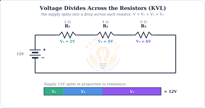
Vsupply = V1 + V2 + V3 + … · Vx = I × Rx
The supply equals the sum of the individual voltage drops; each drop follows Ohm's law
Bigger resistor, bigger share
Because the current is the same, the drop V = IR is proportional to each resistor's value. The 6 Ω resistor gets three times the voltage of the 2 Ω one.
Rule 3: Resistances Simply Add
Adding resistors in series makes the current fight through them one after another, so the total resistance is just the sum of the parts — always larger than any single resistor.

Rtotal = R1 + R2 + R3 + … + Rn
Total (equivalent) resistance of resistors in series
Also true for other components
Inductances in series add just like resistors (Ltotal = L1 + L2 + …). Capacitors are the exception — in series they combine like parallel resistors: 1/Ctotal = 1/C1 + 1/C2 + …
Putting It Together with Ohm's Law
Combine the three rules with Ohm's law and you can solve any series circuit completely. Here is the full worked example for the circuit above.
Worked example — 12 V across 2 Ω, 4 Ω, 6 Ω
1. Total resistance: Rtotal = 2 + 4 + 6 = 12 Ω
2. Circuit current (Ohm's law): I = V / Rtotal = 12 / 12 = 1 A
3. Voltage drops (same 1 A through each):
V1 = 1×2 = 2 V, V2 = 1×4 = 4 V, V3 = 1×6 = 6 V → check: 2+4+6 = 12 V ✓
Quick power check
Total power: P = VI = 12×1 = 12 W. Per resistor: P1=2 W, P2=4 W, P3=6 W.
The powers also add to the total: 2+4+6 = 12 W ✓
The Series Voltage Divider
The most useful trick that falls straight out of series circuits is the voltage divider — two resistors that tap off a chosen fraction of the input voltage.
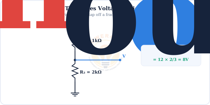
Vout = Vin × R2 / (R1 + R2)
Output voltage tapped between two series resistors
Voltage dividers are everywhere: setting reference voltages, reading sensors (a thermistor or LDR in a divider), scaling a signal down for a microcontroller's ADC, and biasing transistors. They rely entirely on the series rules — same current, proportional voltage drops.
Series vs Parallel Circuits
Series is one of two fundamental ways to connect components. Its opposite, the parallel circuit, gives every component its own path. Here is the side-by-side comparison.
| Property | Series circuit | Parallel circuit |
|---|---|---|
| Paths | One single path | Multiple branches |
| Current | Same everywhere | Divides between branches |
| Voltage | Divides across components | Same across each branch |
| Total resistance | Adds: R1+R2+… (larger) | 1/R1+1/R2+… (smaller) |
| If one fails (open) | Whole circuit stops | Other branches keep working |
| Typical use | Switches, fuses, dividers, LED strings | Mains outlets, home wiring |
Real circuits are often both
Most practical circuits mix the two into series-parallel networks, which you solve by repeatedly collapsing series and parallel groups into single equivalent resistances.
Uses & the Big Limitation
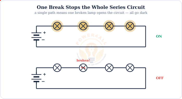
Series connection is simple and cheap, but it has one defining weakness: break the loop anywhere and everything stops.
Switches & fuses
Placed in series so one switch or fuse controls or protects the whole circuit.
LED strings
LEDs in series with one current-limiting resistor share the same current.
Cells in a battery
Cells in series add their voltages — four 1.5 V cells make 6 V.
Voltage dividers
Two series resistors set reference and sensor voltages.
Advantages
Simple, less wire, adds cell voltages, one switch/fuse controls all.
Disadvantages
One break kills all; each part gets less voltage; more parts = less current.
Key Terms at a Glance
The essential series-circuit vocabulary students and engineers search for.
Series circuit
Components on one single path.
Voltage drop
V = IR across a component.
KVL
Drops sum to the supply.
Equivalent resistance
Rtotal = R1+R2+…
Voltage divider
Two series resistors tap a fraction.
Open circuit
A break that stops all current.
Frequently Asked Questions
Quick, expert answers to the questions people ask most about series circuits.
What is a series circuit?
A series circuit is a circuit in which the components are connected one after another so there is only a single path for current. Because there is just one path, the same current flows through every component, and the supply voltage is shared between them.
What are the three rules of a series circuit?
First, the current is the same through every component: I = I1 = I2 = I3. Second, the voltages add up to the supply: V = V1 + V2 + V3. Third, the resistances add up: Rtotal = R1 + R2 + R3.
Is the current the same in a series circuit?
Yes. Because a series circuit has only one path, the same current flows through every component. An ammeter placed anywhere in the loop reads the identical value, so I = I1 = I2 = I3.
How does voltage divide in a series circuit?
The supply voltage divides across the components in proportion to their resistance, and the drops add up to the supply. This is Kirchhoff's voltage law: V = V1 + V2 + V3. A larger resistor takes a larger share of the voltage.
How do you calculate total resistance in a series circuit?
Add the individual resistances together: Rtotal = R1 + R2 + R3 + … For example, 2 Ω, 4 Ω and 6 Ω in series give a total of 12 Ω. The total is always larger than the biggest single resistor.
What happens if one component fails in a series circuit?
If any one component fails open, it breaks the single path and the current stops everywhere, so the whole circuit goes dead. This is why old-style series Christmas lights all went out when a single bulb burned out.
What is the difference between series and parallel circuits?
In a series circuit there is one path, the current is the same everywhere, voltage divides, and resistances add. In a parallel circuit there are multiple paths, the voltage is the same across each branch, the current divides, and the total resistance is less than the smallest branch.
What is a voltage divider?
A voltage divider is two resistors in series used to tap off a fraction of the input voltage. The output taken between them is Vout = Vin × R2 / (R1 + R2). It is a very common way to scale a voltage down.
What are examples of series circuits?
Examples include a torch with cells and a bulb in series, old series-string fairy lights, LEDs in series with a current-limiting resistor, the cells inside a battery pack, and safety chains where a single switch or fuse must break the whole loop.
What are the advantages and disadvantages of series circuits?
Advantages: they are simple, use less wire, add cell voltages, and a single switch or fuse controls the whole circuit. Disadvantages: one break stops everything, components share the voltage so each gets less, and adding more components reduces the current.
Conclusion & Key Takeaways
A series circuit is the simplest circuit of all — one loop, one current — and everything else follows from that single fact.
One path
Components joined end-to-end.
I is constant
Same current everywhere.
V divides
V = V1+V2+V3 (KVL).
R adds
Rtotal = R1+R2+…
Divider
Vout = VinR2/(R1+R2).
One break = all off
The series trade-off.