Buck Converter Calculator
Design and analyze buck (step-down) DC-DC converters for power electronics.
Enter Design Parameters
Enter all parameters and click Calculate.
Given: Vin=200V, Vout=56V, Pout=840W, Ripple=10%, fsw=50kHz
Given: Vin=24V, Vout=12V, Pout=60W, Ripple=20%, fsw=100kHz
Given: Vin=48V, Vout=24V, Pout=120W, Ripple=15%, fsw=75kHz
A buck converter is a switch-mode DC-DC converter that steps a higher input voltage down to a lower, regulated output while wasting very little power. Instead of burning off the excess voltage as heat the way a linear regulator does, it rapidly switches the input on and off and uses an inductor and capacitor to average the result — which is why a well-designed buck converter typically reaches 90–98% efficiency.
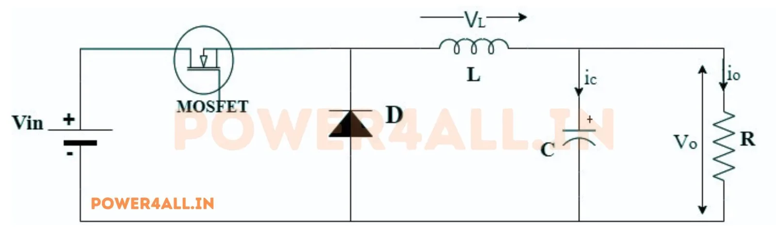
A control switch (usually a MOSFET) connects the input to the inductor for a fraction D of every switching cycle. While the switch is on, current ramps up in the inductor and feeds the load; while it is off, the inductor keeps that current flowing through a diode — or through a second “synchronous” MOSFET in higher-efficiency designs. The output capacitor smooths the pulses into clean DC. The average output is simply Vout = D × Vin, so a 50% duty cycle halves the voltage and a 25% duty cycle quarters it.
The inductor sets how much the current ripples: a larger inductance or a higher switching frequency gives smaller ripple. The calculator above uses L = (Vin − Vout) × D / (ΔIL × fsw). The output capacitor is then sized to hold the voltage ripple within your target. Keeping the ripple current below roughly 30–40% of the load current keeps the converter in continuous conduction mode (CCM), where the formulas hold exactly. At very light load it can slip into discontinuous conduction mode (DCM), where the output tends to rise and regulation behaves differently.
A basic (non-synchronous) buck uses a Schottky diode for the freewheeling path; its forward drop wastes power, which matters most at low output voltages and high currents. A synchronous buck replaces that diode with a MOSFET that is actively switched, cutting conduction loss and pushing efficiency higher — the standard choice for modern low-voltage, high-current rails.
They are everywhere: point-of-load regulators on computer boards (12 V down to 1.2 V for a CPU core), battery-powered gadgets, LED drivers, solar charge controllers, automotive 48 V-to-12 V rails, and industrial supplies. Anywhere a voltage must be lowered efficiently, the buck is the default topology.
Why is my measured output a little below D × Vin? Resistance in the switch, diode and inductor drops a small amount of voltage — expect a few percent, and more at high current.
How do I reduce output ripple? Increase the inductor value, raise the switching frequency, or add more (low-ESR) output capacitance.