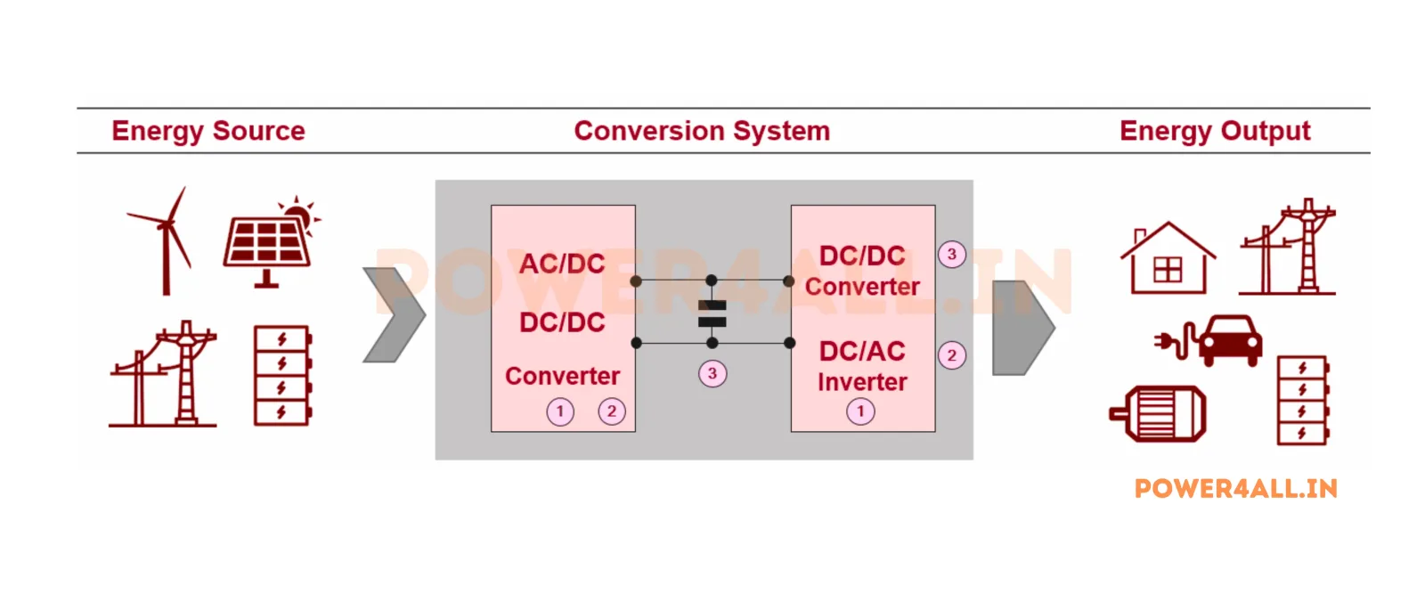
What is Power Electronics?
Comprehensive introduction to power electronics fundamentals and applications.
- Basic principles and concepts
- Applications in modern technology
- Key components and systems
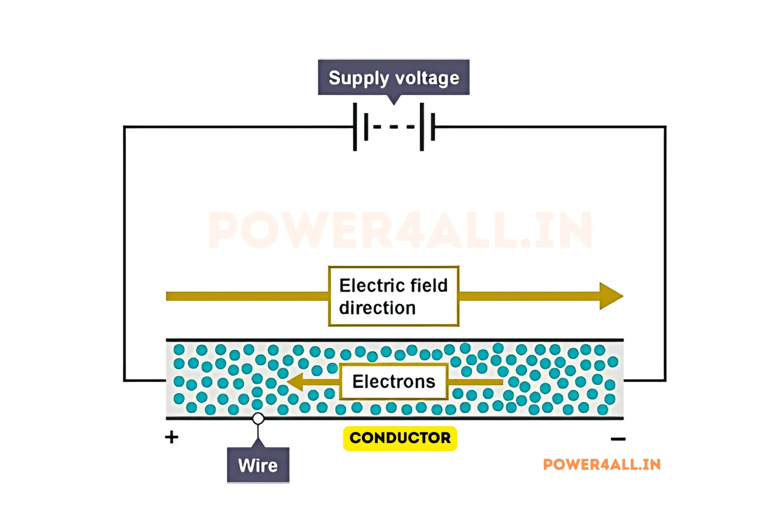
What is Voltage?
Understanding voltage, its measurement, and role in electrical circuits.
- Definition and units
- Measurement techniques
- AC vs DC voltage
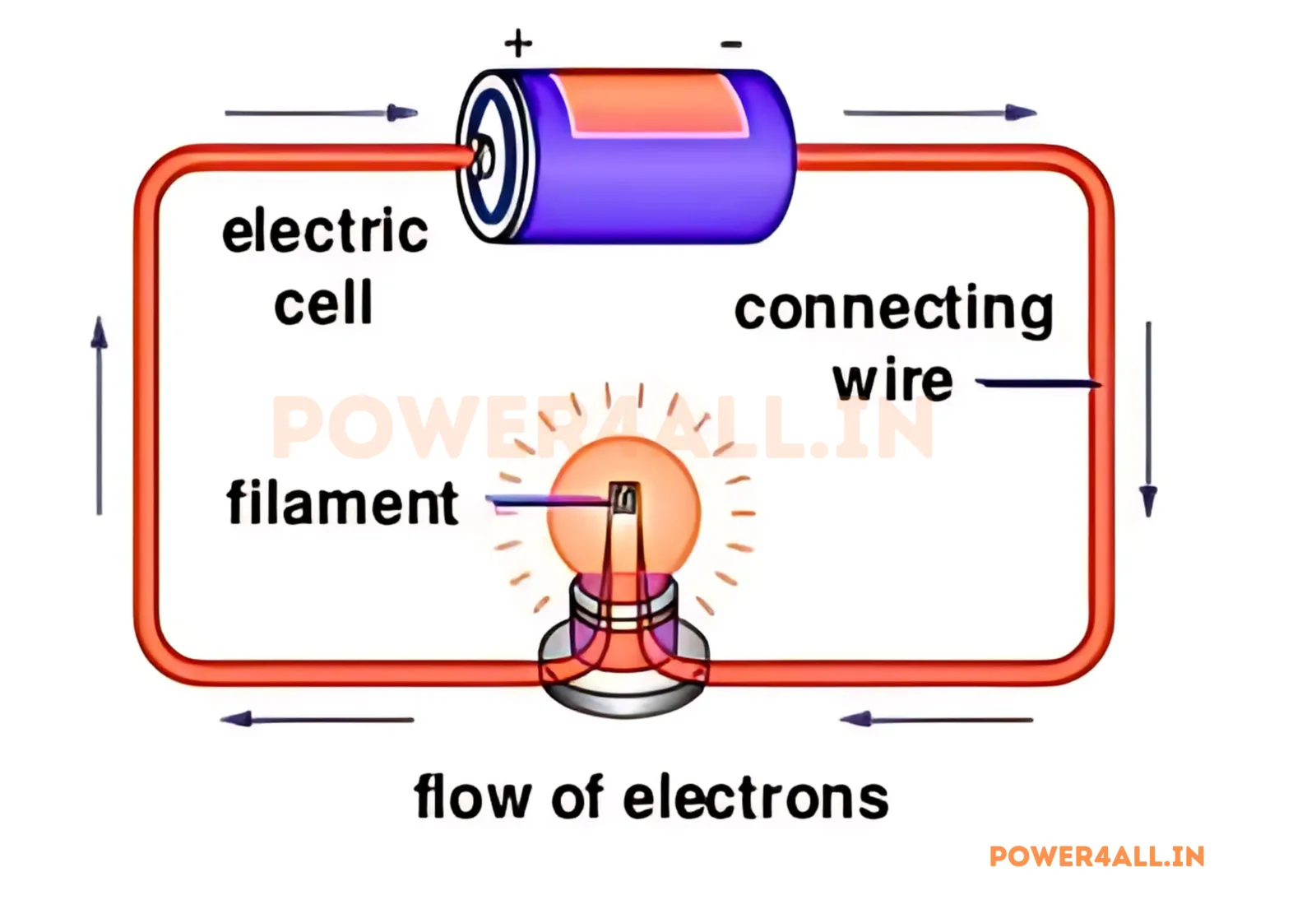
What is Current?
Explore electric current, its types, and measurement in electrical systems.
- Current flow principles
- Types of current
- Current measurement
What is Electric Charge?
Understand electric charge, Coulomb's law, and how charge underpins voltage and current.
- Charge and the coulomb
- Coulomb's law
- Charge in circuits
What is Electric Power?
Explore electric power, watts, the P = VI relationship, AC/DC power and power factor.
- Power and the watt
- P = VI relationship
- AC/DC power & power factor
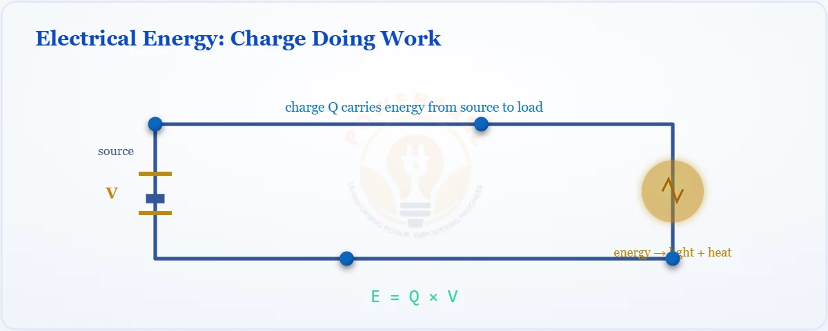
What is Electrical Energy?
Learn electrical energy, the joule and kilowatt-hour, and how E = P × t drives your electricity bill.
- Energy, the joule & kWh
- E = P × t relationship
- Energy cost & billing
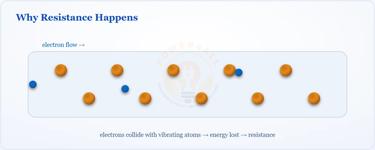
What is Resistance?
Understand electrical resistance, the ohm, and what controls how strongly a material opposes current.
- Resistance & the ohm
- Factors affecting resistance
- Series & parallel resistance
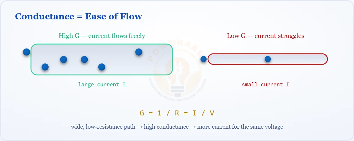
What is Conductance?
Explore conductance (G = 1/R), the siemens, and how easily a material allows current to flow.
- Conductance & the siemens
- G = 1/R relationship
- Use in parallel circuits
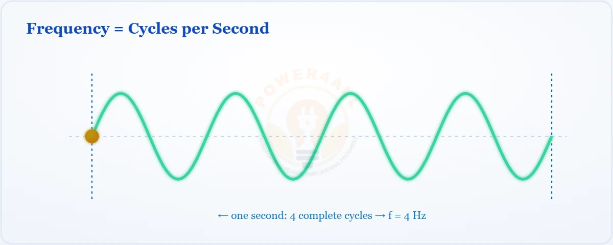
What is Frequency?
Understand frequency, the hertz, period (T = 1/f), and its role in AC systems and signals.
- Frequency & the hertz
- Period, T = 1/f
- AC mains & signal frequency
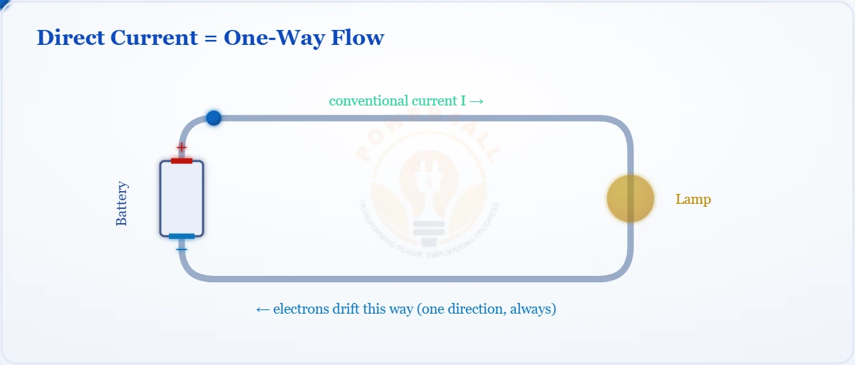
What is Direct Current (DC)?
One-directional current explained — DC vs AC, sources, rectification, pure vs pulsating DC, formulas and uses.
- DC vs AC & sources
- AC-to-DC rectification
- Formulas & applications
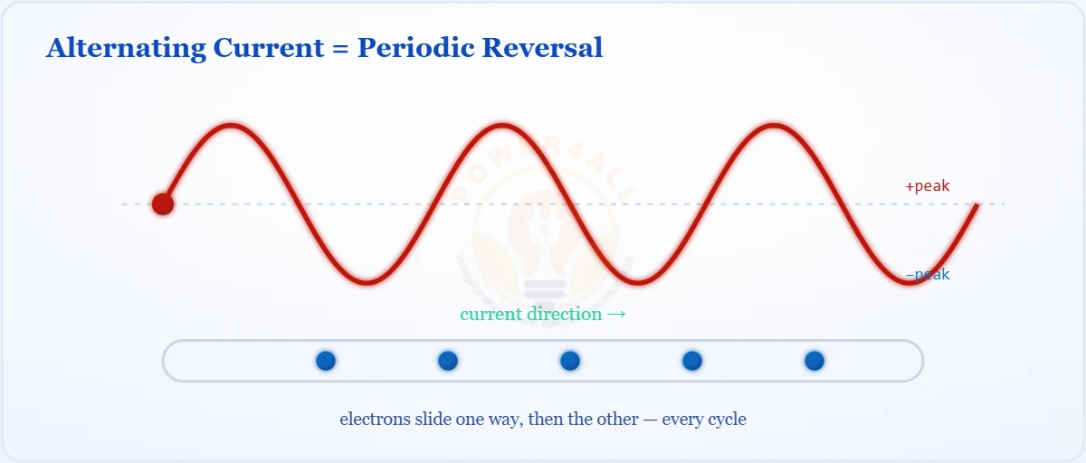
What is Alternating Current (AC)?
The sine-wave current that reverses direction — AC vs DC, generation, peak & RMS, frequency, phases and uses.
- Sine wave & RMS value
- How AC is generated
- Single & three phase
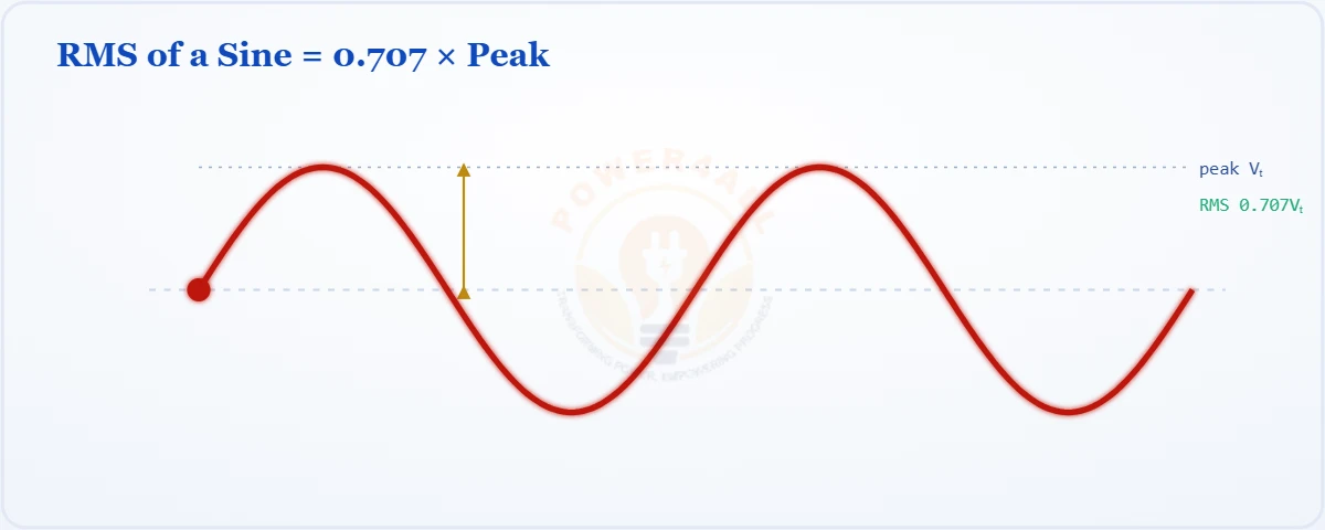
What is RMS Value?
Root mean square — the effective value of AC. Why Vrms = 0.707 × peak, the square–mean–root process, and other waveforms.
- Effective value & heating
- Vrms = Vm/√2
- Form & crest factor
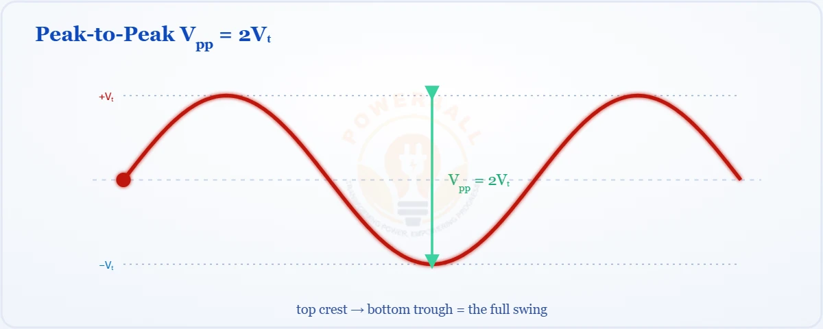
Peak & Peak-to-Peak Value
The peak value (amplitude, Vm) and peak-to-peak (Vpp = 2Vm) — how they relate to RMS, waveform values and ratings.
- Peak Vm & Vpp = 2Vm
- Peak vs RMS vs average
- Conversions & ratings
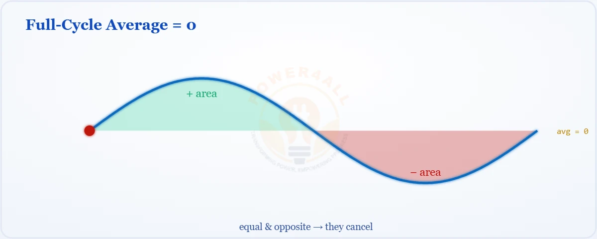
What is Average Value?
The mean of a waveform — why the full cycle is zero, the half-cycle average Vavg = 0.637 Vm, and average vs RMS.
- Full-cycle average = 0
- Vavg = 0.637 Vm
- Average vs RMS & form factor
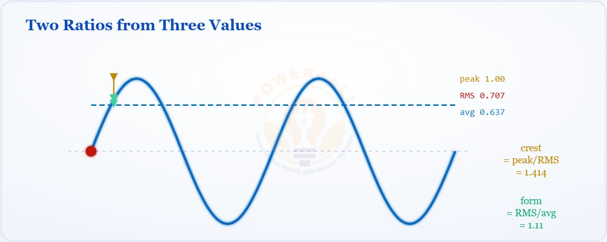
Form & Crest Factor
The two shape ratios of a waveform — form factor (RMS/avg = 1.11) and crest factor (peak/RMS = 1.414), with waveform values and uses.
- Form factor = 1.11 (sine)
- Crest factor = 1.414 (sine)
- Meter calibration & stress
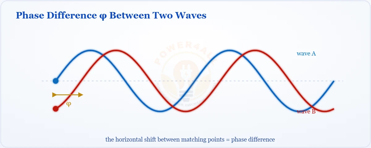
Phase & Phase Difference
The phase angle φ and the offset between two waves — in-phase, quadrature, anti-phase, leading vs lagging and phase in R, L, C.
- Phase angle & difference
- Leading vs lagging (ELI/ICE)
- Phasors & power factor
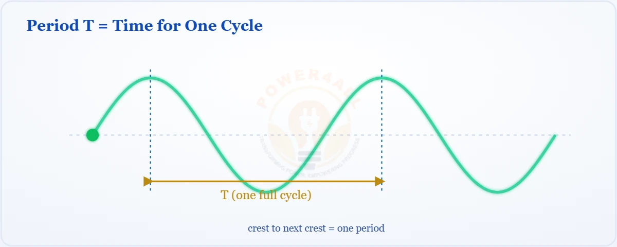
Period & Frequency
The period T (time for one cycle) and frequency f (cycles per second), the reciprocal T = 1/f, units and mains examples.
- T = 1/f reciprocal
- Units (s, ms, µs, ns)
- 50 Hz → 20 ms & ω = 2π/T
What is Impedance (Z)?
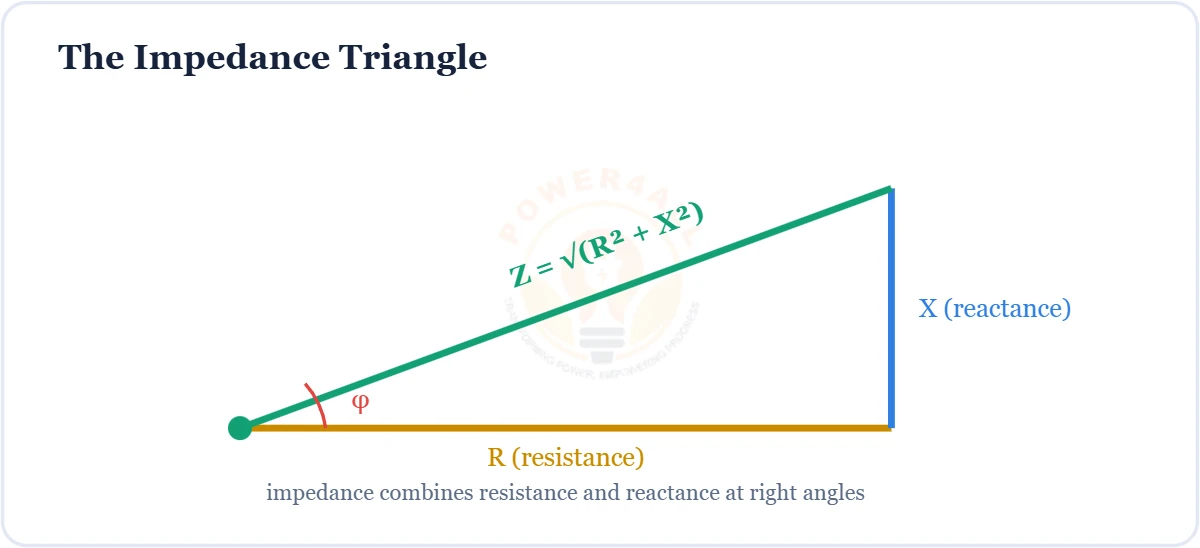
Total AC opposition — Z = R + jX, the impedance triangle, R/L/C impedance, frequency response and Ohm's law for AC.
- Z = R + jX & the triangle
- Impedance of R, L, C
- V = I × Z (AC Ohm’s law)
Reactance (XL & XC)
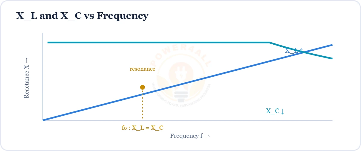
The AC opposition of inductors & capacitors — XL = 2πfL rises with frequency, XC = 1/2πfC falls, plus phase and resonance.
- XL = 2πfL, XC = 1/2πfC
- Net reactance & resonance
- 90° phase (ELI the ICE man)
What is Admittance (Y)?
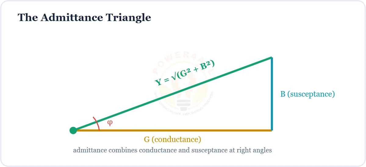
The ease of AC flow — Y = 1/Z, Y = G + jB, conductance & susceptance, and why admittances add in parallel circuits.
- Y = 1/Z & Y = G + jB
- Conductance & susceptance
- Admittances add in parallel
Q Factor & Bandwidth
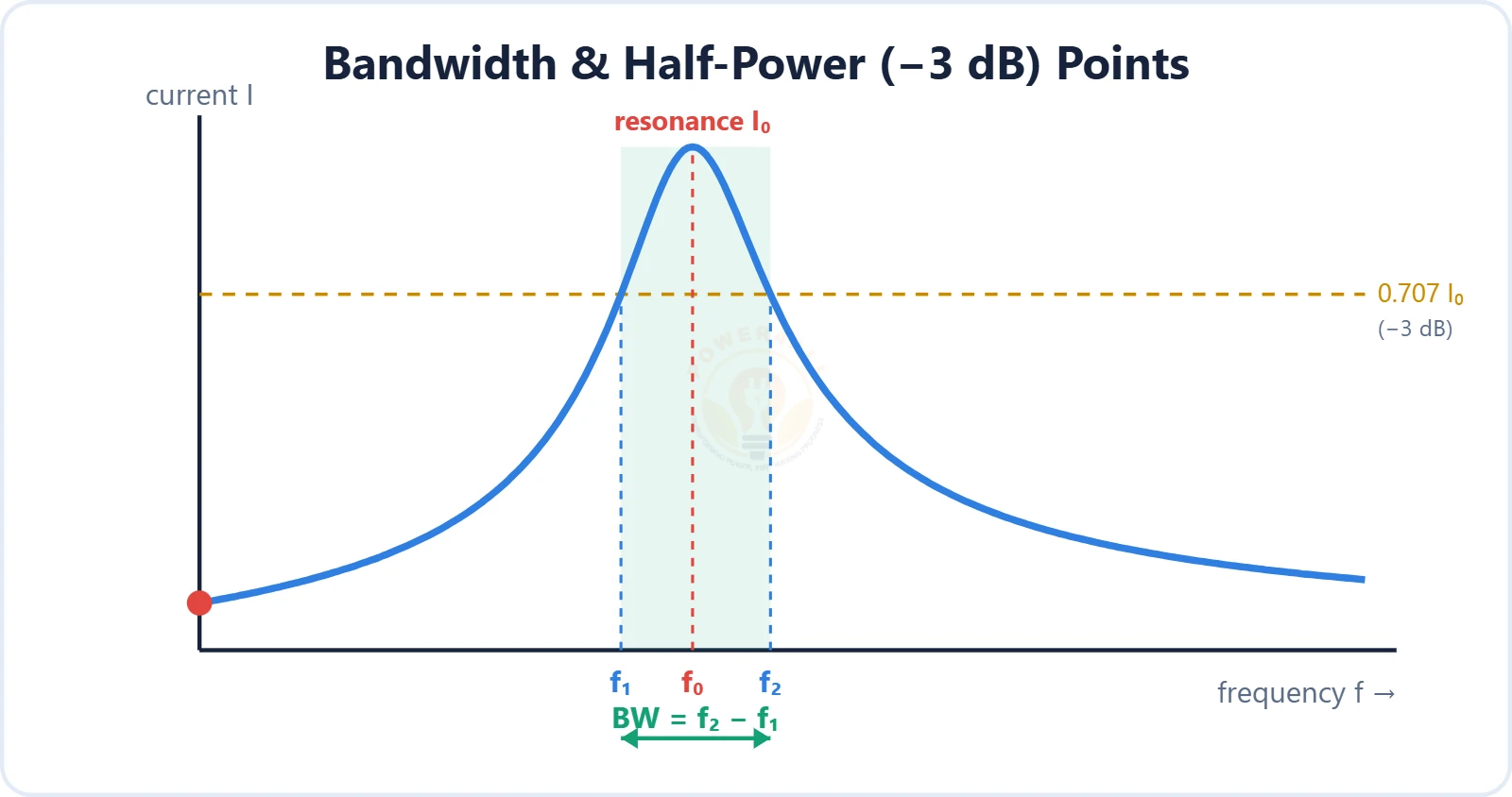
The sharpness of resonance — quality factor Q, bandwidth between the half-power (−3 dB) points, and the link Q = f₀/BW, with RLC formulas and the energy definition.
- Q = f₀/BW & BW = f₂ − f₁
- Half-power (−3 dB) points
- Q = (1/R)√(L/C) & energy ratio
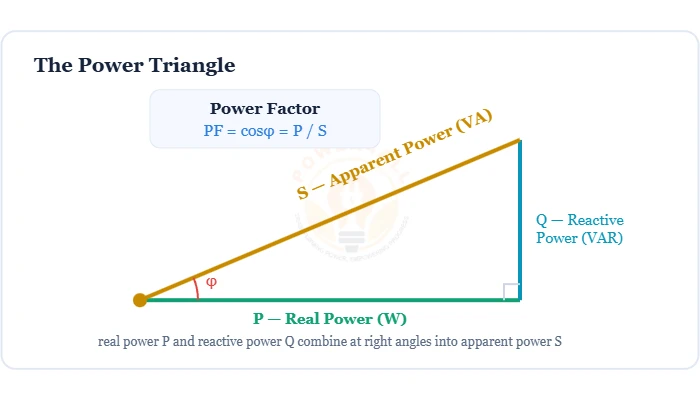
What is Power Factor (cos φ)?
How much supplied power does useful work — PF = cosφ = P/S, the power triangle, leading vs lagging PF, and correction with capacitors.
- PF = cosφ = P / S (0–1)
- Real, reactive & apparent power
- Leading vs lagging & PF correction
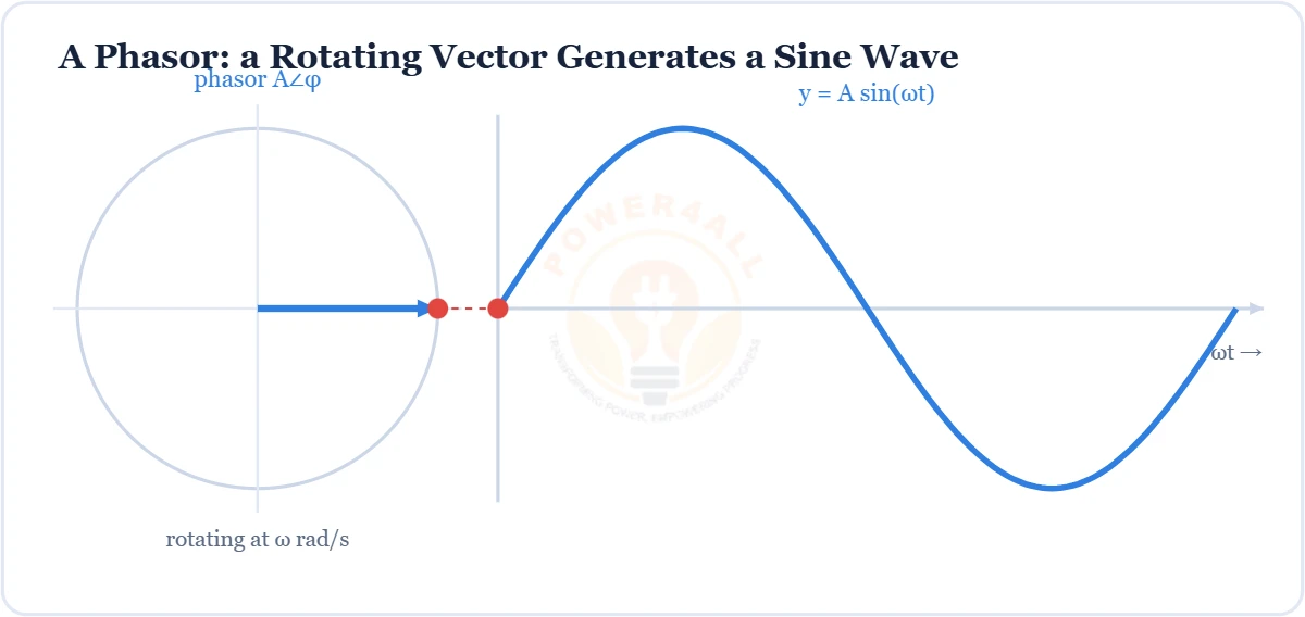
Phasors & Complex Numbers
The rotating-vector tool that makes AC analysis easy — the j operator, rectangular a + jb & polar r∠θ forms, phasor arithmetic and circuit diagrams.
- Phasor = magnitude & phase (A∠φ)
- a + jb ↔ r∠θ & the j operator
- Add rect, multiply polar; Z = R + jX
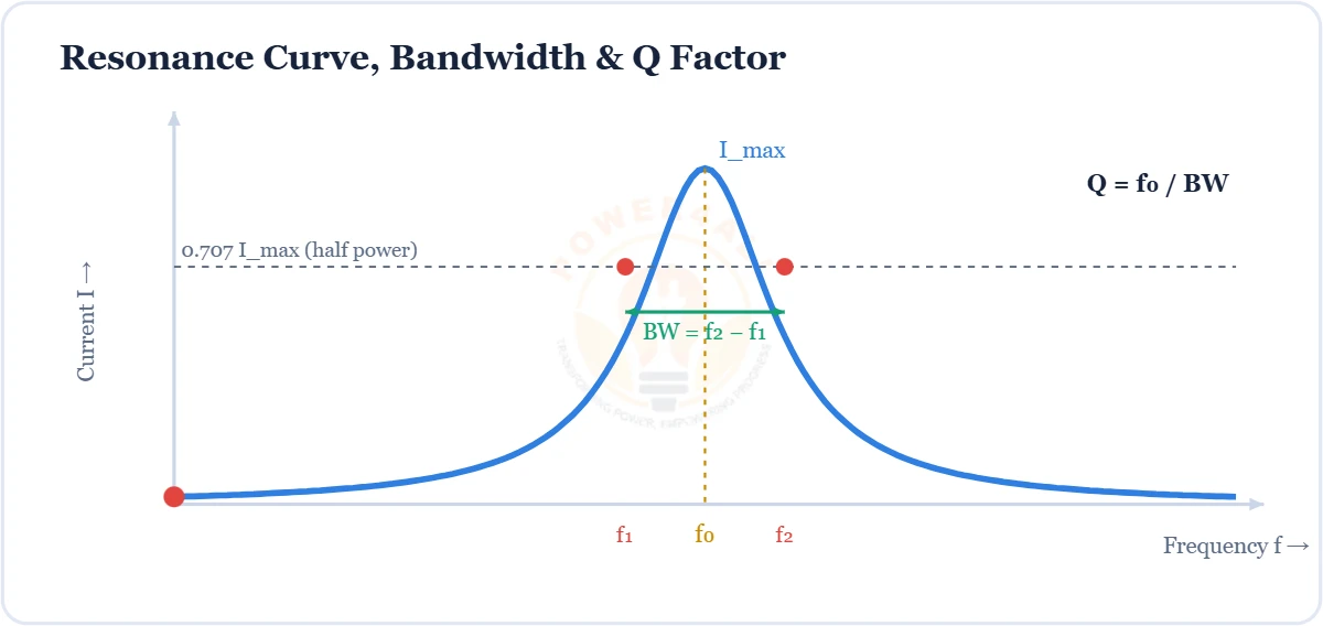
Resonance (Series & Parallel)
When XL = XC and reactances cancel — f0 = 1/2π√(LC), series (Z min) vs parallel tank (Z max), plus Q factor and bandwidth.
- f0 = 1/2π√(LC), XL = XC
- Series Z min / parallel Z max
- Q factor, bandwidth & selectivity
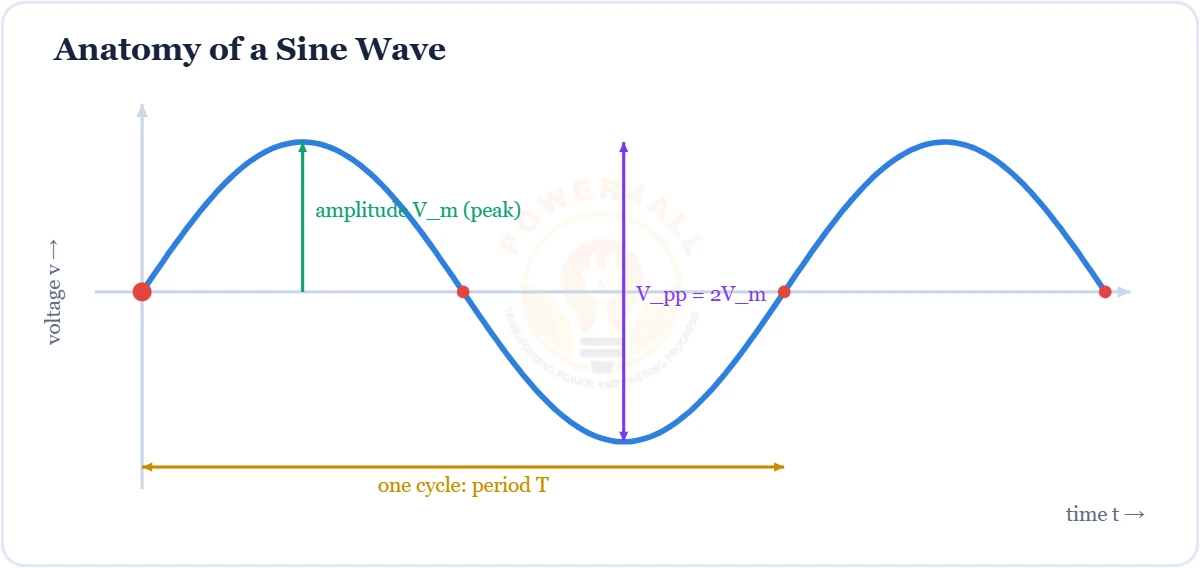
Sine Wave
The pure, fundamental AC waveform — v(t) = Vm sin(2πft + φ), with amplitude, period, frequency, phase and peak / RMS / average values.
- v(t) = Vm sin(2πft + φ)
- Amplitude, period T, f = 1/T, phase φ
- Vrms = 0.707Vm, Vavg = 0.637Vm
Square Wave
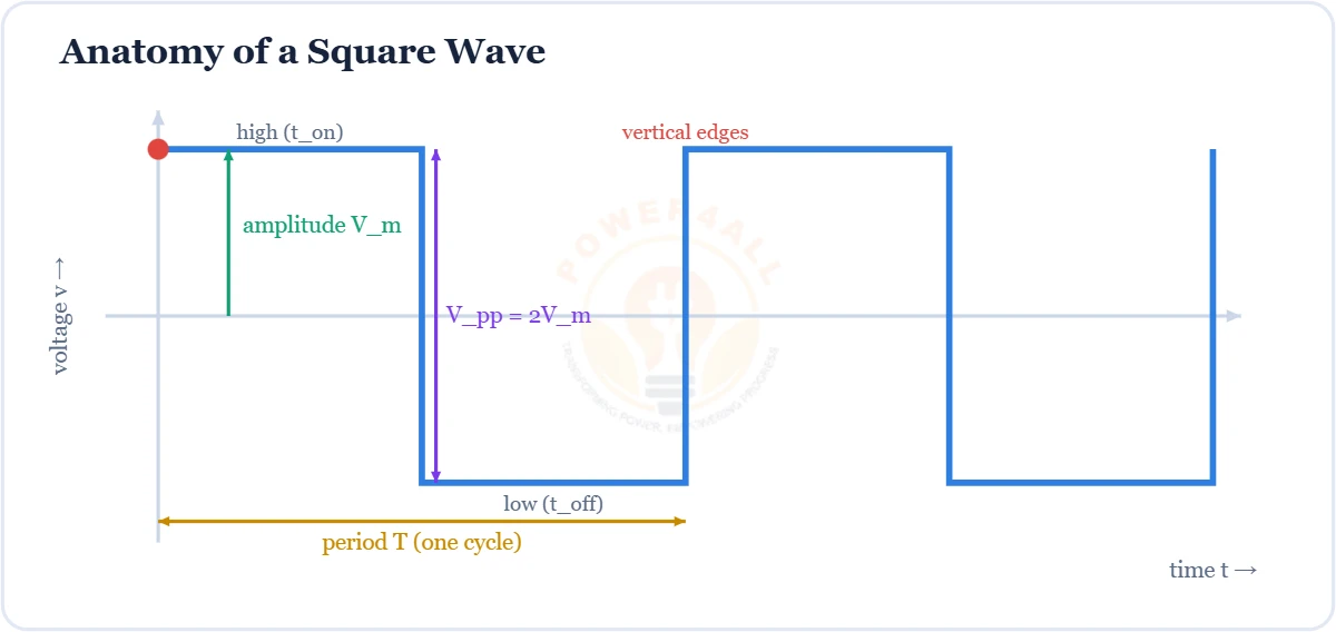
The two-level ON/OFF waveform of digital & switching circuits — duty cycle D = ton/T, odd-harmonic Fourier series, spectrum, RMS values and PWM.
- Duty cycle D = ton/T (PWM)
- Odd harmonics: f, 3f, 5f… (1/n)
- Vrms = Vm; square vs sine
Real, Reactive & Apparent Power
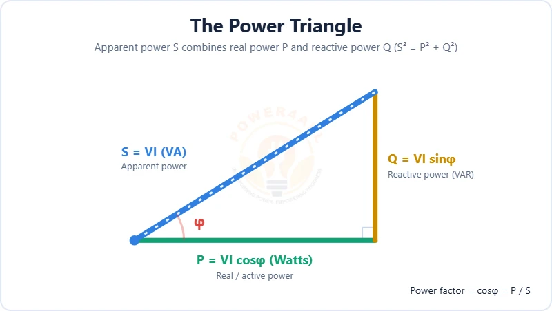
The three kinds of AC power and how they fit together — real power P = VI cosφ (W), reactive power Q = VI sinφ (VAR) and apparent power S = VI (VA), plus the power triangle and power factor.
- P = VI cosφ, Q = VI sinφ, S = VI
- Power triangle S² = P² + Q²
- Power factor cosφ = P/S & the beer analogy
Harmonics & THD
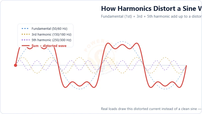
The extra frequencies that distort AC and how we measure them — harmonic order, odd/even/triplen harmonics, the THD formula, the spectrum, nonlinear-load sources, effects and mitigation.
- Harmonic n at n× the fundamental
- THD = √(V₂²+V₃²+…)/V₁
- Triplen harmonics & the neutral
Three-Phase Systems
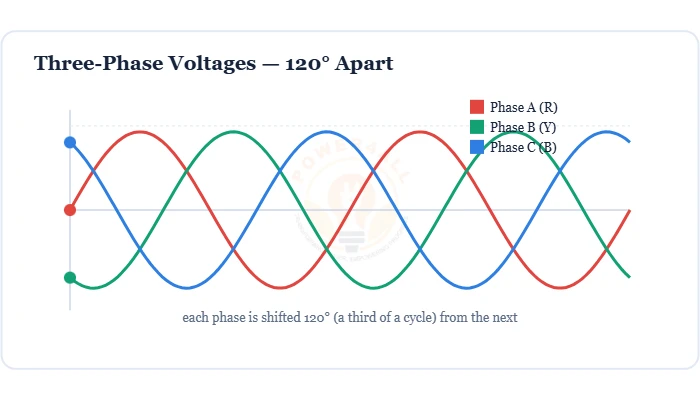
Three AC voltages 120° apart that power the grid — star vs delta, line vs phase (√3), three-phase power P = √3 VLILcosφ and why it beats single-phase.
- Three phases 120° apart (R, Y, B)
- Star & delta; VL = √3 Vph
- P = √3 VLILcosφ; 400/230 V
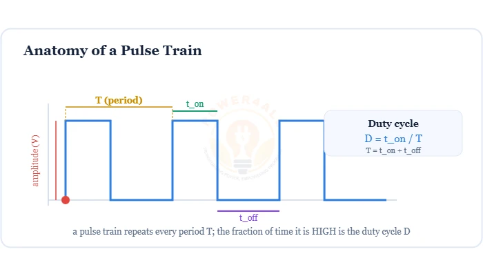
Pulse & PWM Signals
The on/off waveform that controls motors, LEDs & power supplies — pulse anatomy, duty cycle D = ton/T, average voltage Vavg = D×Vin and SPWM generation.
- Duty cycle D = ton/T (0–100%)
- Vavg = D × Vin
- SPWM & motor / LED control
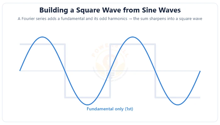
Fourier Series Basics
How any periodic waveform is a sum of sine waves — the Fourier series formula f(t) = a₀/2 + ∑(aₙcos nωt + bₙsin nωt), fundamental & harmonics, building a square wave, symmetry, the spectrum & the Gibbs phenomenon.
- f(t) = a₀/2 + ∑(aₙcos nωt + bₙsin nωt)
- Square wave = odd harmonics (1/n)
- Line spectrum & Gibbs overshoot
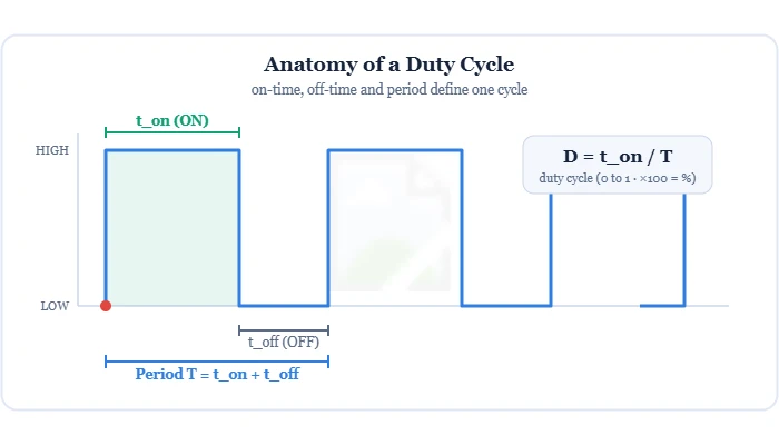
Duty Cycle
The fraction of each cycle a signal is ON — duty cycle D = ton/T (0–100%), how it sets the average voltage Vavg = D×V, complementary duty & dead-time, and PWM control of motors, LEDs & power supplies.
- D = ton/T (0–100%)
- Vavg = D × Vsupply
- Complementary duty & dead-time
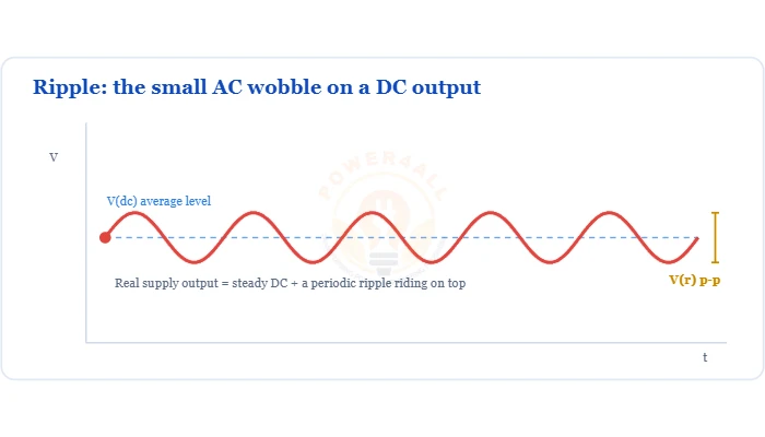
What is Ripple & Ripple Factor?
How much AC is left on a rectifier’s DC output, and the ripple factor that measures it.
- Ripple factor γ = Vr(rms)/Vdc
- Half-wave 1.21 vs full-wave 0.48
- Capacitor smoothing & reduction
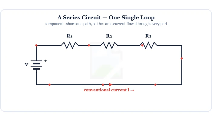
Series Circuits
Components on one single path — the same current flows through every part, the supply voltage divides across them (V = V1+V2+V3), and resistances add up. Covers KVL, Ohm's law, the voltage divider & series vs parallel.
- Same current: I = I1 = I2 = I3
- V = V1 + V2 + V3 (KVL)
- Rtotal = R1 + R2 + R3
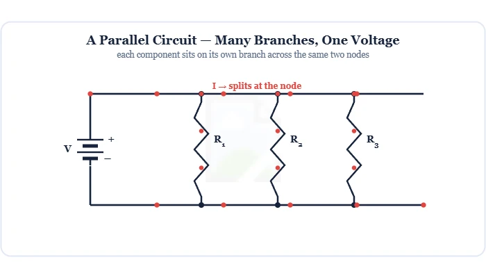
Parallel Circuits
Components on separate branches across the same two nodes — the same voltage across each (V = V1 = V2), the current divides (I = I1+I2+I3), and total resistance is less than the smallest. Covers KCL, the current divider & why homes are wired this way.
- Same voltage: V = V1 = V2
- I = I1 + I2 + I3 (KCL)
- 1/Rtotal = 1/R1 + 1/R2
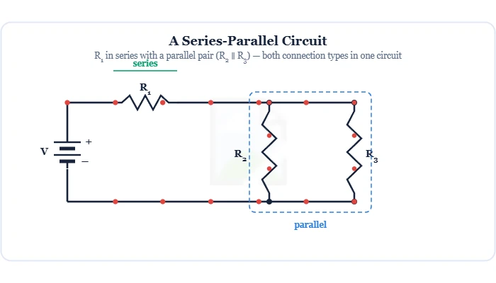
Series-Parallel Circuits
Combined networks that mix series and parallel connections. Learn to spot the groups and solve them by step-by-step reduction (combine parallel first, then series), with worked examples, ladder networks and the loaded voltage divider.
- Reduce: parallel first, then series
- Equivalent resistance & back-solve
- Ladder networks & loaded dividers
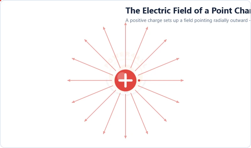
Electric Field
The invisible region of force around every charge. Learn the definition E = F/q, field lines and direction, the dipole, point-charge strength E = kQ/r² and the uniform field between capacitor plates E = V/d.
- E = F/q · unit N/C = V/m
- Field lines: + out, − in; the dipole
- E = kQ/r² & uniform field E = V/d
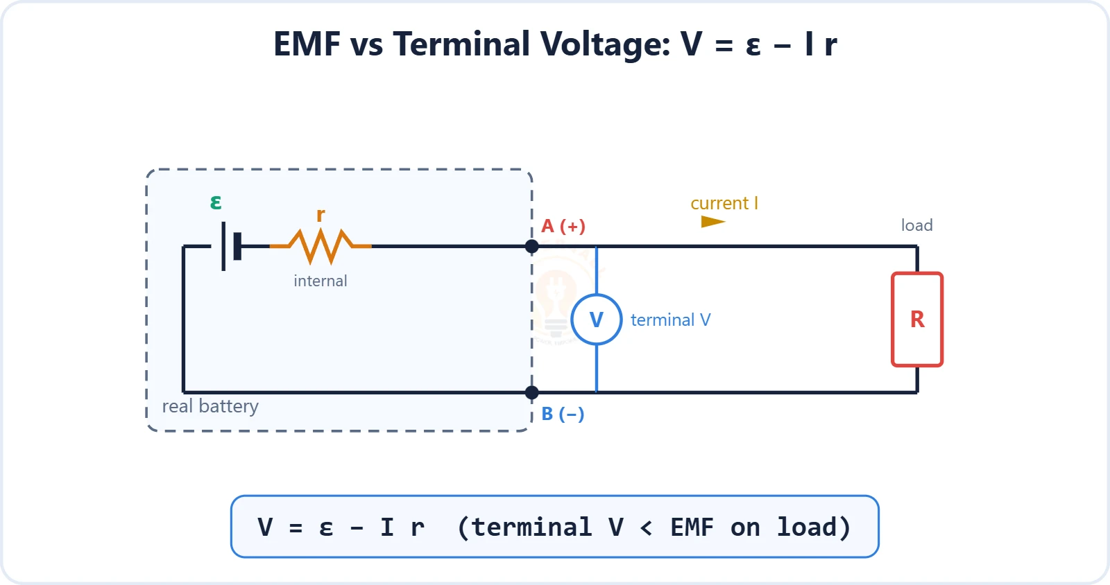
Electromotive Force (EMF)
The driving energy a source gives per unit charge — EMF ε = W/Q, why it isn't really a force, EMF vs terminal voltage with internal resistance (V = ε − Ir), sources of EMF and cells in series & parallel.
- EMF ε = W/Q, unit volt
- Terminal voltage V = ε − Ir & internal resistance
- Sources of EMF & cell combinations
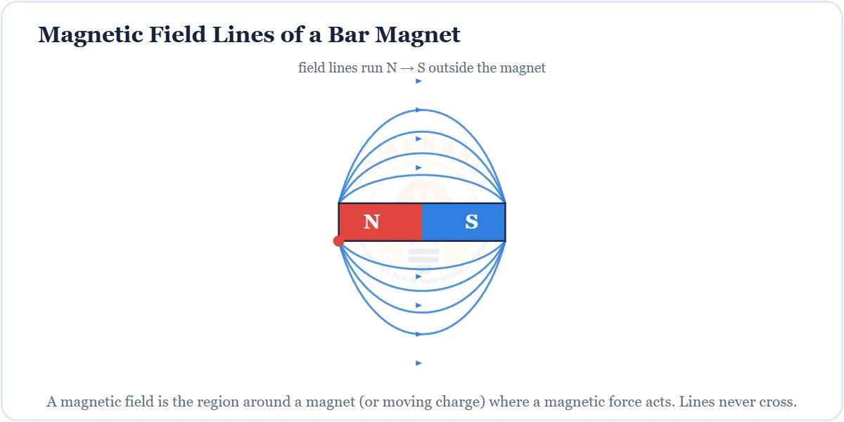
Magnetic Field
The region around a magnet or current where a magnetic force acts — field lines, the right-hand rule, flux density B = Φ/A, force F = BIL and the B–H curve.
- Field lines & right-hand rule
- Flux density B = Φ/A (tesla)
- Force F = BIL; solenoids & B–H
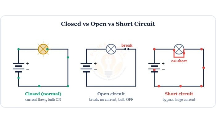
Open & Short Circuits
The two opposite circuit faults — an open circuit is a break (infinite R, no current), a short circuit is a zero-Ω bypass (huge current). Difference, causes, dangers & protection.
- Open = break, ∞ R, I = 0
- Short = 0Ω path, I very large
- Causes, fuses/MCBs & testing
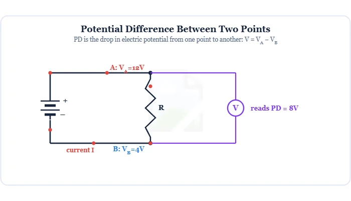
Potential Difference
The difference in electric potential between two points — the energy per charge (V = W/Q) that drives current. Covers the volt, electric potential & reference, PD vs EMF and terminal voltage (V = ε − Ir), and measuring PD with a voltmeter.
- V = W/Q (1 V = 1 J/C)
- PD vs EMF: V = ε − Ir
- Voltmeter measures across (parallel)
Grounding & Earthing
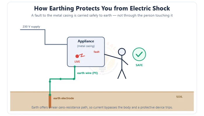
The safety connection to earth that prevents electric shock — grounding vs earthing, the earth-fault loop, types of earthing (plate/pipe/rod), TN/TT/IT systems, earth resistance & the earth pit.
- Fault current → earth, not through you
- Plate, pipe & rod earthing; TN/TT/IT
- Earth resistance ≤ 1–5 Ω
What is Watt's Law (Power Law)?
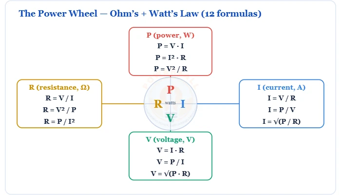
Power = voltage × current, its three forms, and the 12-formula power wheel.
- P = V·I = I²R = V²/R
- Power triangle & power wheel
- Why 2× current = 4× power
Faraday's Law
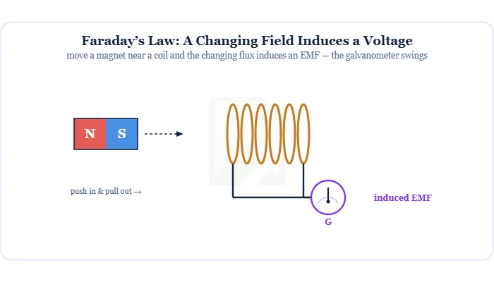
Electromagnetic induction — a changing magnetic flux induces a voltage: EMF = −N dΦ/dt. Covers magnetic flux (Φ = BA cosθ), Lenz's law & the minus sign, the three ways to induce an EMF, and the AC generator behind the grid.
- EMF = −N dΦ/dt
- Magnetic flux Φ = BA cosθ
- Lenz's law & the AC generator
Lenz's Law
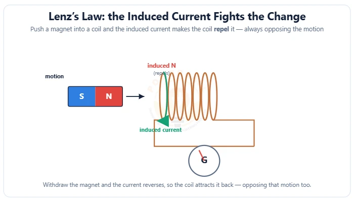
The direction rule of induction — the induced current always opposes the change in flux that creates it. The minus sign in EMF = −N dΦ/dt, finding the direction, the copper-tube demo, eddy currents & energy conservation.
- Induced current opposes the change
- The − sign in EMF = −N dΦ/dt
- Eddy currents & braking
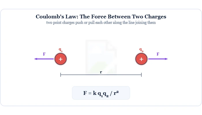
Coulomb's Law
The electrostatic force between two charges: F = k q1q2/r2. Covers the Coulomb constant (8.99×10⁹), why like charges repel & unlike attract, the inverse-square law, superposition, and the link to the electric field.
- F = k q1q2 / r2
- Like repel, unlike attract
- Inverse-square & superposition
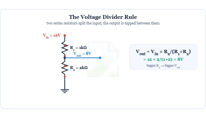
Voltage Divider Rule
Two series resistors split a voltage: Vout = Vin·R2/(R1+R2). Covers the derivation, resistor ratios, multi-resistor taps, the loading effect, and the potentiometer as an adjustable divider.
- Vout = Vin·R2/(R1+R2)
- Equal resistors → half the input
- Loading effect & potentiometer
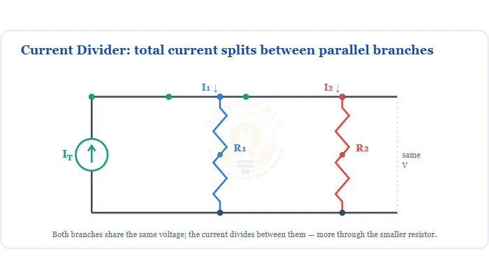
What is the Current Divider Rule?
How current splits between parallel branches — the opposite-resistor formula and conductance form.
- I₁ = IT·R₂/(R₁+R₂)
- Opposite resistor on top
- Smaller R carries more current
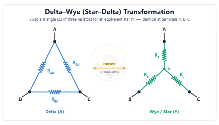
Delta-Wye (Star-Delta) Transformation
Swap a triangle (Δ) of resistors for an equivalent star (Y) — and back. The Δ→Y and Y→Δ formulas, the balanced case RΔ = 3RY, worked examples and cracking bridge circuits.
- Δ ↔ Y (π ↔ T) networks
- Adjacent-product ÷ sum; P ÷ opposite arm
- Solves unbalanced bridge circuits
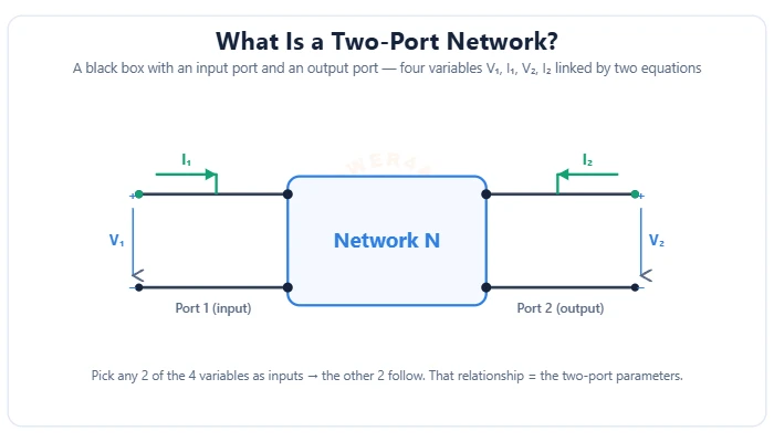
Two-Port Networks
Model any circuit as a black box with an input & output port — four variables V1, I1, V2, I2. The Z, Y, h & ABCD parameters, their open/short-circuit tests, the transistor h-model & the cascade rule.
- 4 variables, 2 equations
- Z, Y, h & ABCD parameter sets
- Cascade → multiply ABCD matrices
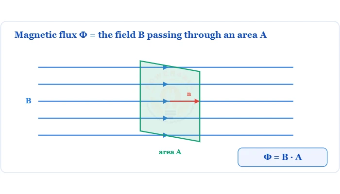
What is Magnetic Flux (Φ)?
The total magnetic field through an area — Φ = B·A·cosθ, the weber, flux density and Faraday's law.
- Φ = B·A·cosθ · unit weber (Wb)
- Flux density B = Φ/A & flux linkage NΦ
- Faraday's law & the magnetic circuit
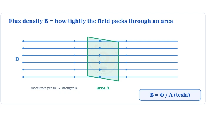
What is Flux Density (B)?
The magnetic field per unit area — B = Φ/A in tesla, permeability, the force F = BIL and typical values.
- B = Φ/A · unit tesla (Wb/m²)
- B = μ₀μᵣH & the force F = BIL
- Earth 50µT to MRI & lab magnets
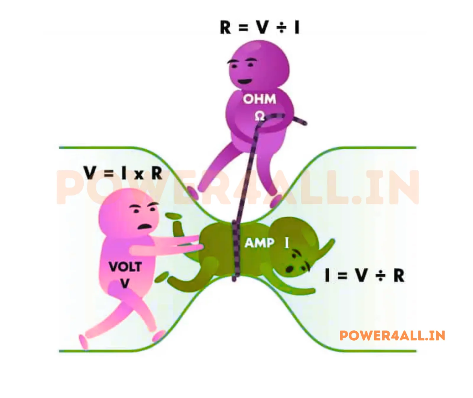
What is Ohm's Law?
Fundamental relationship between voltage, current, and resistance.
- V = I × R relationship
- Practical applications
- Problem solving techniques
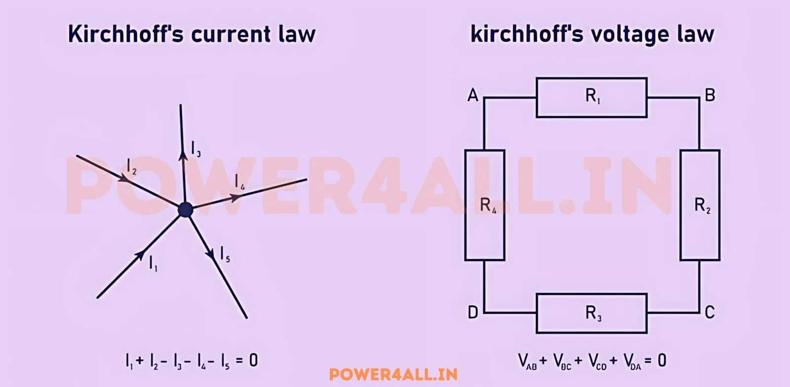
What is Kirchhoff's Law?
Current and voltage laws for analyzing electrical circuits.
- Kirchhoff's Current Law (KCL)
- Kirchhoff's Voltage Law (KVL)
- Circuit analysis applications
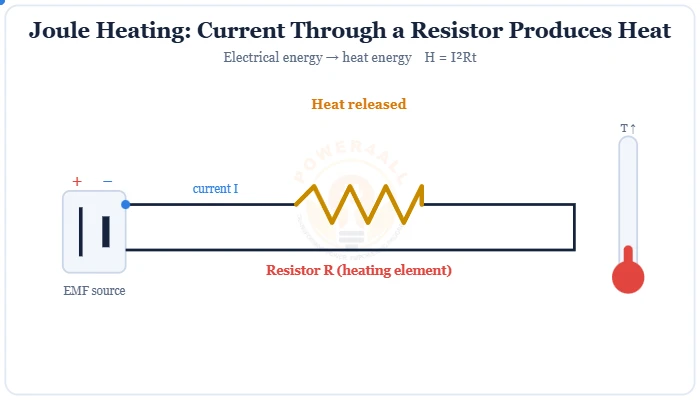
What is Joule's Law of Heating?
The heating effect of current: how much heat a resistance produces, H = I²Rt.
- H = I²Rt formula & derivation
- Heaters, bulbs & the fuse
- Joules, calories & I²R losses
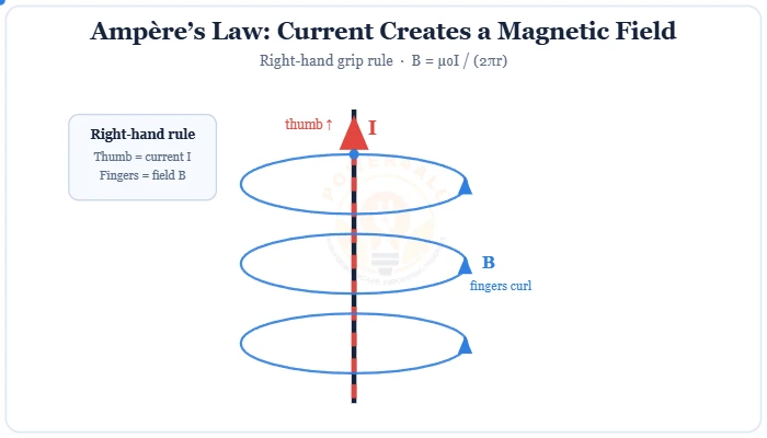
What is Ampère's Law?
The magnetic effect of current: the field around a loop, ∮B·dl = µ₀I.
- Circuital law & right-hand rule
- Wire, solenoid & toroid fields
- Ampère–Maxwell displacement current
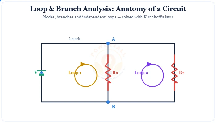
What is Loop & Branch Analysis?
Solve any circuit with Kirchhoff's laws: the branch-current & loop-current methods.
- Branch, node, loop & mesh
- Independent loops L = b − n + 1
- Worked two-loop example
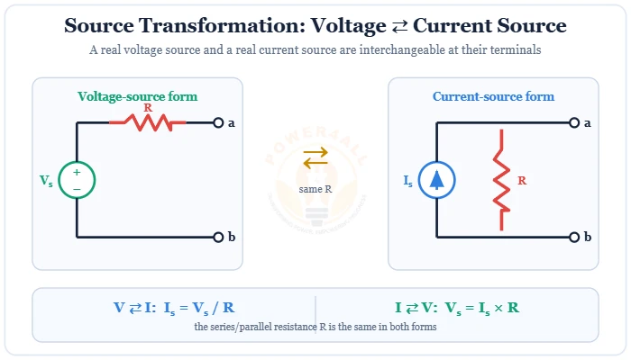
What is Source Transformation?
Swap a voltage source (series R) for a current source (parallel R): I = V/R, V = I×R.
- Voltage ⇄ current source
- Rules, conditions & example
- Thévenin ⇄ Norton bridge
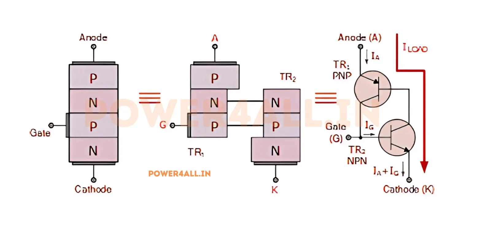
What is SCR?
Silicon Controlled Rectifier - a powerful semiconductor switching device.
- Three-terminal device
- Gate triggering mechanism
- Power control applications
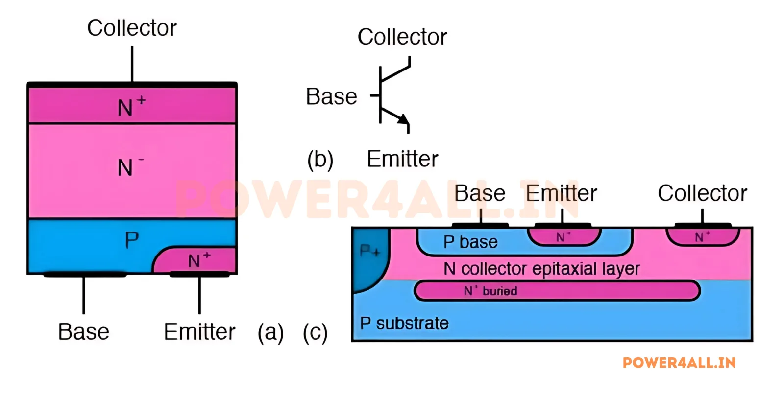
What is BJT Transistor?
Bipolar Junction Transistor for amplification and switching applications.
- NPN and PNP types
- Current amplification
- Switching characteristics
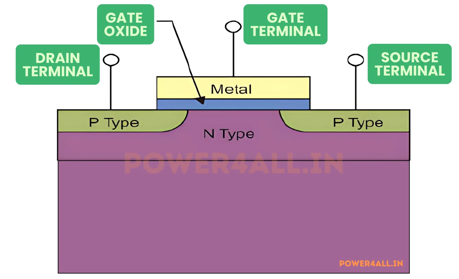
What is MOSFET Transistor?
Metal-Oxide-Semiconductor Field-Effect Transistor for efficient switching.
- Voltage-controlled device
- High switching speeds
- Low power consumption
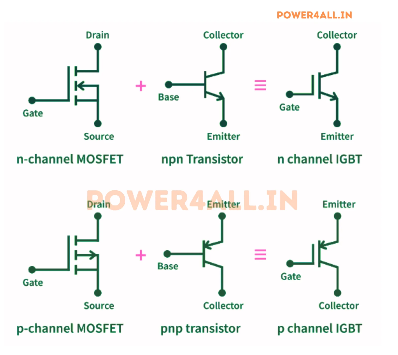
What is IGBT Transistor?
Insulated Gate Bipolar Transistor combining MOSFET and BJT advantages.
- High voltage capability
- Fast switching
- Power electronics applications
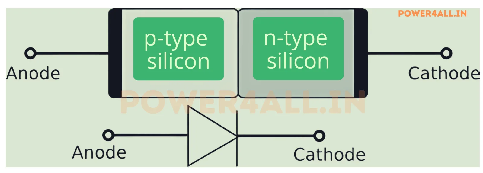
What is Diode?
Fundamental semiconductor device allowing current flow in one direction.
- PN junction structure
- Forward and reverse bias
- Rectification applications
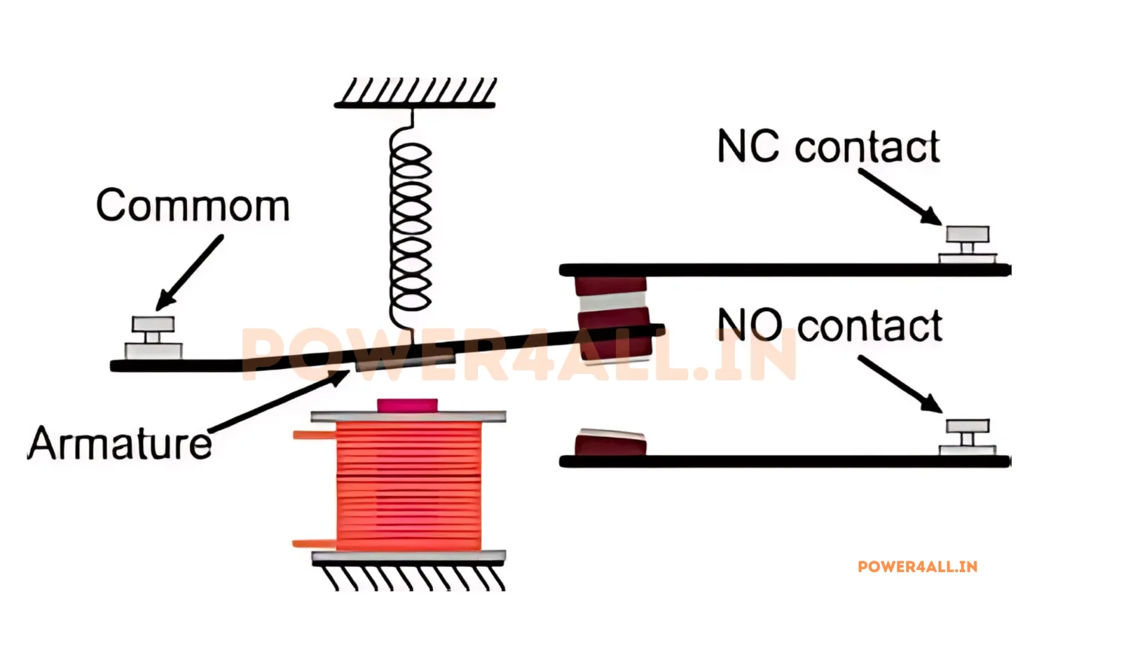
What is Relay?
Electrically operated switch that uses electromagnetic principles for control.
- Electromagnetic switching
- Contact types and ratings
- Control applications
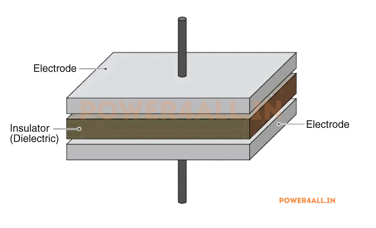
What is Capacitor?
Energy storage device that stores electrical charge and opposes voltage changes.
- Charge storage mechanism
- Types and applications
- Charging and discharging
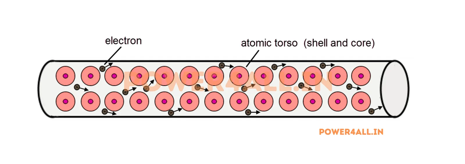
What are Resistors?
Basic passive components that oppose current flow and control voltage levels.
- Resistance and Ohm's law
- Types and color coding
- Power ratings
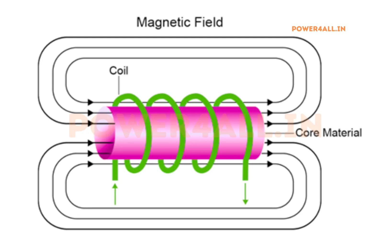
What is Inductor?
Passive component that stores energy in magnetic field and opposes current changes.
- Magnetic energy storage
- Inductance and reactance
- AC and DC behavior
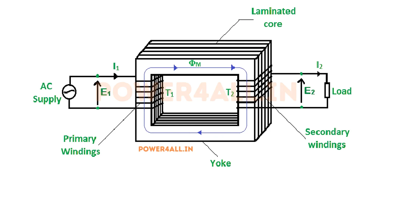
What is Transformer?
Device that transfers electrical energy between circuits through electromagnetic induction.
- Voltage transformation
- Step-up and step-down
- Isolation and efficiency