The Voltage Divider Rule
The complete guide to the voltage divider rule (VDR) — how two series resistors split a voltage. From the formula Vout = Vin·R2/(R1+R2) and its derivation, to resistor ratios, multiple taps, the loading effect, and the potentiometer.
Complete Learning Path — Voltage Divider Rule
From the formula and derivation, to ratios, multiple taps, the loading effect and the potentiometer
The Rule & the Formula
The voltage divider rule is one of the most-used shortcuts in electronics: put two resistors in series across a voltage, and the voltage splits between them in proportion to their resistances. Tap the point between them and you get a smaller, predictable voltage.

Vout = Vin × R2 / (R1 + R2)
Output across R2 — the input times R2's share of the total resistance
Worked example
Vin = 12 V, R1 = 1 kΩ, R2 = 2 kΩ.
Vout = 12 × 2/(1+2) = 12 × 2/3 = 8 V
Need it fast?
Skip the algebra with the Voltage Divider Calculator — enter Vin, R1 and R2 and read Vout instantly.
Where the Rule Comes From
The rule is not magic — it falls straight out of the series-circuit facts and Ohm's law in three short steps.

I = Vin/(R1+R2) → Vout = I·R2 → Vout = Vin·R2/(R1+R2)
One current sets both drops, so the output is just R2's share
The Ratio Sets the Output
Only the ratio matters. Vout is the same fraction of Vin as R2 is of the total resistance.

| R1 : R2 | Fraction R2/(R1+R2) | Vout (on 12 V) |
|---|---|---|
| 1 : 1 | 1/2 | 6 V |
| 3 : 1 | 1/4 | 3 V |
| 1 : 3 | 3/4 | 9 V |
| 1 : 5 | 5/6 | 10 V |
Two equal resistors halve the voltage
The most common case: R1 = R2 gives exactly half the input, whatever the actual value.
More Than Two Resistors
A series string of resistors gives several taps, each at a different voltage. The rule generalises neatly.
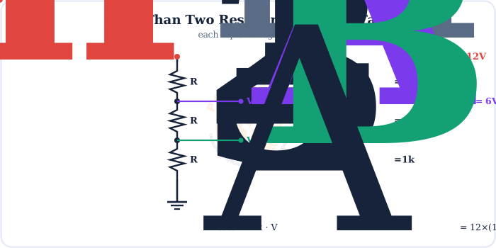
Vx = Vin × Rbelow x / Rtotal
Voltage from any tap to the bottom rail, for resistors in series
This is exactly how a resistor ladder makes several reference voltages from one supply, and how an R-2R ladder converts digital codes to analog voltages.
The Loading Effect
The catch: the tidy formula assumes nothing draws current from the tap. Connect a real load and it forms a series-parallel circuit — and the output drops.

Rule of thumb
Keep the load resistance much larger than R2 (say 10× or more) so it barely disturbs the divider — or buffer the tap with an op-amp follower. A resistive divider sets a reference, it does not power things.
The Potentiometer: An Adjustable Divider
Make the split adjustable and you have a potentiometer — a resistive track with a sliding wiper that taps any voltage from 0 to Vin.

The wiper splits the track into a top part (acting as R1) and a bottom part (R2). Volume knobs, light dimmers, joystick and throttle position sensors are all potentiometer dividers — the same rule, made variable.
Where the Voltage Divider Rule Is Used
It is one of the first tools every electronics designer reaches for.
Sensor reading
A thermistor or LDR in a divider turns resistance change into a voltage a chip can read.
Scaling for an ADC
Divide a high voltage down into a microcontroller's safe input range.
Reference voltages
Set a fixed bias or threshold for comparators and op-amps.
Transistor biasing
A divider sets the base voltage that biases a transistor stage.
Volume & tone
Potentiometer dividers set audio level and tone in amplifiers.
Dimmers & controls
Adjustable dividers set brightness, speed and position.
Key Terms at a Glance
The essential voltage-divider vocabulary students and engineers search for.
Voltage divider
Series resistors that split a voltage.
Vout
The tapped output voltage.
Divider ratio
R2/(R1+R2).
Loading effect
A load pulling Vout down.
Potentiometer
An adjustable divider with a wiper.
Tap
The node the output is taken from.
Frequently Asked Questions
Quick, expert answers to the questions people ask most about the voltage divider rule.
What is the voltage divider rule?
The voltage divider rule states that two resistors in series split the input voltage in proportion to their resistances. The voltage across one resistor equals the input voltage times that resistor divided by the total resistance.
What is the voltage divider formula?
For two series resistors R1 (top) and R2 (bottom) with the output taken across R2, the formula is Vout = Vin × R2/(R1 + R2).
How do you calculate the output of a voltage divider?
Add the two resistances, divide the output resistor by that total, and multiply by the input voltage. For example, with Vin = 12 V, R1 = 1k and R2 = 2k, Vout = 12 × 2/(1+2) = 8 V.
Does the voltage divider rule work with more than two resistors?
Yes. With several resistors in series, the voltage from any tap to the bottom equals the input times the sum of the resistances below the tap divided by the total resistance. Each tap gives a different fraction of the input.
Why does a load change a voltage divider's output?
Connecting a load across the lower resistor puts it in parallel, lowering that resistance and therefore its share of the voltage. So the output sags below the no-load value. This loading effect is why dividers use low resistances or a buffer when driving a real load.
What is a potentiometer?
A potentiometer is a resistor with a sliding contact called a wiper. It acts as an adjustable voltage divider: moving the wiper taps any voltage between zero and the input. Volume knobs, dimmers and joystick sensors use potentiometers this way.
Can a voltage divider supply current to a load?
Only a little. A resistive divider is meant to set a reference voltage, not to power a load. Drawing significant current loads the divider and drops the output, so for real loads you buffer the output with an op-amp or use a proper regulator.
What is the difference between a voltage divider and a current divider?
A voltage divider uses series resistors to split a voltage, with the output proportional to the resistor. A current divider uses parallel resistors to split a current, with more current going through the smaller resistance. They are duals of each other.
Where are voltage dividers used?
They set reference voltages, scale a signal down for a microcontroller's analog input, read resistive sensors like thermistors and light-dependent resistors, bias transistors, and form the volume and tone controls in audio equipment.
How do you choose resistor values for a voltage divider?
Pick the ratio R2/(R1+R2) to give the fraction you want, then choose the actual values so the divider draws a small but sensible current. Too high and noise and loading matter; too low and it wastes power. Values in the kilohm range are common.
Conclusion & Key Takeaways
The voltage divider rule turns two resistors into a precise, predictable way to scale a voltage — simple, and everywhere.
Vout = VinR2/(R1+R2)
The core formula.
Ratio rules
Output tracks R2's share.
Equal = half
R1 = R2 → Vin/2.
Many taps
Resistance below / total.
Mind the load
Keep RL >> R2.
Pot = adjustable
Wiper taps 0…Vin.