Resonance in Series & Parallel Circuits
The complete guide to electrical resonance — the special frequency where inductive and capacitive reactances cancel. From f0 = 1/2π√(LC) to series resonance (minimum impedance), parallel tank resonance (maximum impedance), Q factor and bandwidth.
Complete Learning Path — Resonance
From the resonance condition and resonant frequency, through series and parallel resonance, to Q factor, bandwidth and real applications
What is Resonance?
Electrical resonance is the condition where a circuit’s inductive reactance and capacitive reactance are equal and cancel. The circuit then behaves as a pure resistance — voltage and current are in phase, and the power factor is 1.
Because inductive reactance XL = 2πfL rises with frequency while capacitive reactance XC = 1/2πfC falls, there is exactly one frequency where they match. That is the resonant frequency f0.
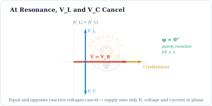
XL = XC → f0 = 1 / (2π√(LC))
The resonance condition and the resonant frequency (ω0 = 1/√(LC))
Worked example
With L = 100 mH and C = 100 µF:
f0 = 1 / (2π√(0.1 × 100×10⁻⁶)) ≈ 50.3 Hz. A radio-scale 100 µH, 100 pF pair resonates near 1.59 MHz.
Same f0, opposite behaviour
Series and parallel circuits resonate at the same basic frequency, but do opposite things: a series circuit becomes a low-impedance short, a parallel tank becomes a high-impedance block.
Series Resonance: Minimum Impedance, Maximum Current
In a series RLC circuit the reactances subtract inside the impedance Z = R + j(XL − XC). At resonance that bracket is zero, so Z drops to just R — its lowest possible value.
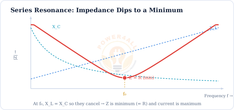
Zmin = R · Imax = V / R
At series resonance impedance is minimum and current is maximum
Voltage magnification
Even though the reactances cancel overall, the individual voltages across L and C can be Q times larger than the supply. That is why an unwanted series resonance can destroy components with over-voltage.
Parallel Resonance: Maximum Impedance (Tank Circuit)
A parallel LC circuit — a tank circuit — is the mirror image. At resonance the branch currents in L and C are equal and opposite, so almost no current is drawn from the supply: the impedance is at its maximum.
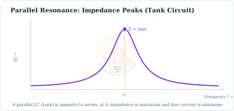
f0 = 1 / (2π√(LC)) · Zmax (line current minimum)
Ideal parallel resonance — energy circulates between L and C, little is drawn from the supply
Energy sloshes back and forth
Inside a tank at resonance, energy oscillates between the inductor’s magnetic field and the capacitor’s electric field, twice per cycle — the electrical version of a swinging pendulum. This is the heart of oscillators and tuners.
Series vs Parallel Resonance
Same formula, opposite effect. Knowing which is which is the whole point.
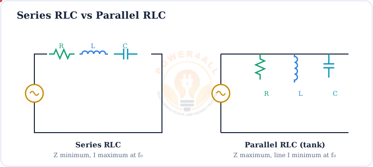
| Property | Series Resonance | Parallel Resonance |
|---|---|---|
| Resonant frequency | f0 = 1/2π√(LC) | f0 = 1/2π√(LC) |
| Impedance at f0 | Minimum (= R) | Maximum |
| Current at f0 | Maximum (V/R) | Minimum (line current) |
| Also called | Acceptor circuit | Rejector / tank circuit |
| Magnifies | Voltage (across L, C) | Current (circulating in L, C) |
| Q factor | ω0L / R | R / ω0L = ω0CR |
Acceptor vs rejector
A series circuit accepts its resonant frequency (lets maximum current through); a parallel circuit rejects it (blocks it with high impedance). This is exactly how band-pass and band-stop filters are built.
Q Factor & Bandwidth
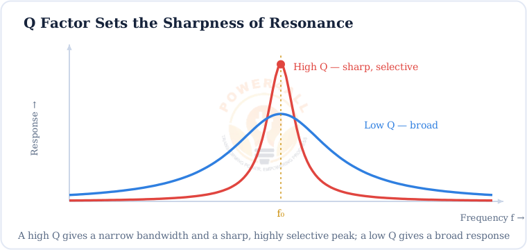
Resonance is never infinitely sharp — resistance broadens it. The quality factor Q measures how sharp and selective the peak is.
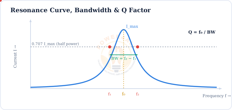
Q = f0 / BW · BW = f2 − f1 = f0 / Q
Quality factor, bandwidth and the half-power (−3 dB) points
Qseries = ω0L / R = (1/R)√(L/C)
Series Q from the circuit values — more L or less R means a higher, sharper Q
Worked example
A series circuit with f0 = 50.3 Hz, L = 100 mH, R = 10 Ω:
Q = ω0L/R = (2π×50.3×0.1)/10 ≈ 3.16, so BW = f0/Q ≈ 15.9 Hz.
Compute f0 instantly with the RLC Resonant Frequency Calculator.
Where Resonance Is Used (and Avoided)
Resonance is one of the most exploited — and most feared — effects in electrical engineering.
Radio & TV tuning
A tank circuit selects one station’s frequency from thousands, rejecting the rest.
Filters
Series (acceptor) and parallel (rejector) resonance build band-pass and band-stop filters.
Oscillators
LC tanks set the frequency of signal generators and clocks.
Induction heating
Resonant converters deliver large currents to heat metal efficiently.
Wireless power
Resonant coupling transfers energy efficiently between coils tuned to the same f0.
Power systems (avoid!)
Accidental resonance with cables and capacitor banks causes damaging over-voltages.
See also the LLC Resonant Converter Calculator and the Reactance Calculator.
Key Terms at a Glance
The essential resonance vocabulary students and engineers search for.
Resonance
XL = XC; circuit is purely resistive.
Resonant frequency
f0 = 1/2π√(LC).
Series resonance
Z minimum, I maximum (acceptor).
Parallel resonance
Z maximum, line I minimum (rejector/tank).
Q factor
Q = f0/BW; sharpness.
Bandwidth
BW = f2 − f1 at half power.
Half-power points
0.707 × peak (−3 dB).
Tank circuit
Parallel L-C storing oscillating energy.
Frequently Asked Questions
Quick, expert answers to the questions people ask most about resonance.
What is resonance in simple words?
Resonance is when a circuit’s inductor and capacitor push back on the AC by exactly the same amount, so their effects cancel. The circuit then acts like a plain resistor, and it responds most strongly at that one frequency — the resonant frequency.
What is the resonant frequency formula?
f0 = 1 / (2π√(LC)), with L in henries and C in farads. In angular form ω0 = 1/√(LC). It sets where XL = XC.
What is the difference between series and parallel resonance?
Series resonance gives minimum impedance (= R) and maximum current, so it accepts the frequency. Parallel (tank) resonance gives maximum impedance and minimum line current, so it rejects the frequency. Both use f0 = 1/2π√(LC).
Why is current maximum at series resonance?
Because XL and XC cancel, the impedance drops to just the resistance R — its smallest value. By Ohm’s law I = V/Z, the smallest Z gives the largest current, Imax = V/R.
What is a tank circuit?
An inductor and capacitor in parallel. At resonance it shows a very high impedance and stores energy that oscillates between the coil and the capacitor, like a pendulum. It is used to tune and to generate single frequencies.
What is the Q factor?
The quality factor measures how sharp and selective the resonance is: Q = f0/BW, and for a series circuit Q = ω0L/R. High Q means a narrow bandwidth and a tall, sharp peak.
What is bandwidth in resonance?
The band of frequencies between the two half-power points (where the response is 0.707 of the peak, i.e. −3 dB). It equals BW = f2 − f1 = f0/Q.
Can resonance be dangerous?
Yes. At series resonance the voltages across L and C can be many times the supply voltage (voltage magnification by Q). In power systems, accidental resonance between line inductance and capacitor banks can cause damaging over-voltages, so it is deliberately avoided there.
Conclusion & Key Takeaways
Resonance is where reactances cancel and a circuit responds most strongly — the basis of every tuner, oscillator and filter.
XL = XC
The resonance condition.
f0 = 1/2π√(LC)
The resonant frequency.
Series → Z min
Maximum current (acceptor).
Parallel → Z max
Minimum line current (tank).
Q = f0/BW
Sharpness & selectivity.
φ = 0, PF = 1
Purely resistive at f0.