Phasors & Complex Numbers
The complete guide to the tool that makes AC circuit analysis easy. A phasor is a rotating vector that captures a sinusoid’s magnitude and phase — from the j operator and the complex plane to rectangular a + jb, polar r∠θ, phasor arithmetic and how it all solves real circuits.
Complete Learning Path — Phasors & Complex Numbers
From the rotating-vector idea, through the j operator and the two number forms, to phasor arithmetic and AC circuit analysis
What is a Phasor?
A phasor is a rotating vector that represents a sinusoidal voltage or current by just two numbers — its magnitude (amplitude) and its phase angle. It is the single most useful tool in AC circuit analysis.
Every sinusoid in a linear circuit oscillates at the same frequency, so the only things that actually differ from one signal to the next are how big they are and when they peak. A phasor throws away the common rotation and keeps exactly those two facts. Picture an arrow of length A spinning anticlockwise at angular frequency ω = 2πf; its vertical shadow traces the wave y = A sin(ωt). Freeze the arrow at t = 0 and you have the phasor.
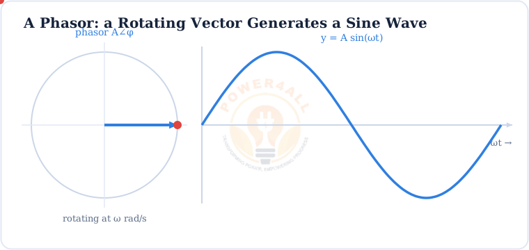
Why bother? Calculus becomes algebra
Without phasors, an AC circuit is a set of differential equations (because inductors and capacitors involve rates of change). Represent each sinusoid as a phasor — a complex number — and those equations collapse into ordinary algebra. That is the whole reason phasors exist.
Complex Numbers & the j Operator
A phasor is really a complex number. To handle magnitude and phase together, we need a plane, not a line — and that means the imaginary unit.
Electrical engineers call it j (not i, which is reserved for current). It is defined by j = √−1, so that j² = −1. On the complex plane (also called the Argand diagram), the horizontal axis is the real part and the vertical axis is the imaginary part. A complex number is a point — or a vector to that point.
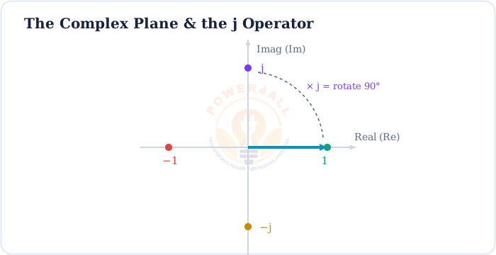
j = √−1 · j² = −1 · j³ = −j · j⁴ = 1
The imaginary unit and its powers — each multiplication by j is a 90° rotation
Two Ways to Write a Phasor: Rectangular & Polar
Every complex number — every phasor — can be written two equivalent ways. Knowing when to use each is the key skill.
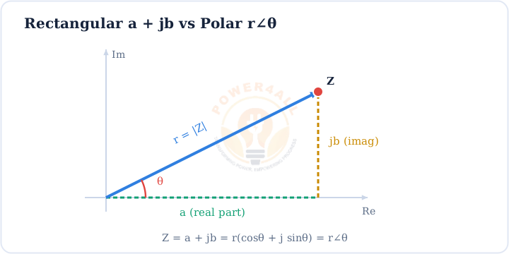
Rectangular form
Z = a + jb
a = real part, b = imaginary part. Best for addition and subtraction.
Polar form
Z = r∠θ
r = magnitude (modulus), θ = angle (argument). Best for multiplication and division.
Trigonometric form
Z = r(cosθ + j sinθ)
The bridge between the two — and the root of Euler’s formula.
Exponential form
Z = r ejθ
Euler’s formula: ejθ = cosθ + j sinθ. Compact and powerful.
Modulus and argument
The magnitude r is the modulus written |Z|; the angle θ is the argument written arg Z. For a voltage or current phasor, r is the amplitude (or RMS value) and θ is the phase.
Converting Between Rectangular & Polar
Because addition wants rectangular form and multiplication wants polar form, you will convert constantly. It is just right-angle trigonometry.
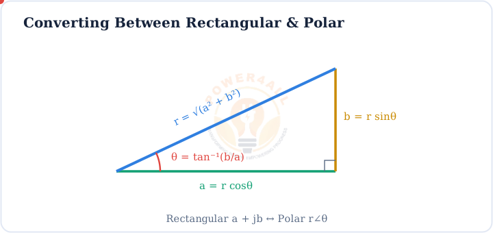
r = √(a² + b²) · θ = tan⁻¹(b / a)
Rectangular → Polar (mind the quadrant of θ)
a = r cosθ · b = r sinθ
Polar → Rectangular
Worked example — rectangular to polar
Convert Z = 3 + j4 to polar form:
r = √(3² + 4²) = √25 = 5 and θ = tan⁻¹(4/3) ≈ 53.13°, so Z = 5∠53.13°.
Worked example — polar to rectangular
Convert Z = 10∠30° to rectangular form:
a = 10 cos30° ≈ 8.66 and b = 10 sin30° = 5, so Z = 8.66 + j5.
Skip the arithmetic with the Complex Number & Phasor Calculator.
Phasor Arithmetic: Add in Rectangular, Multiply in Polar
The two forms exist because each makes a different operation trivial. Pick the right one and phasor algebra is easy.
| Operation | Use this form | Rule |
|---|---|---|
| Addition | Rectangular | (a₁+a₂) + j(b₁+b₂) |
| Subtraction | Rectangular | (a₁−a₂) + j(b₁−b₂) |
| Multiplication | Polar | r₁r₂ ∠(θ₁+θ₂) — multiply magnitudes, add angles |
| Division | Polar | (r₁/r₂) ∠(θ₁−θ₂) — divide magnitudes, subtract angles |
Worked example — Ohm’s law with phasors
A current I = 2∠20° A flows through an impedance Z = 5∠40° Ω. The voltage is:
V = I × Z = (2×5) ∠(20°+40°) = 10∠60° V. Multiplication in polar form is one line.
The conjugate trick
To divide in rectangular form, multiply top and bottom by the complex conjugate of the denominator (flip the sign of its imaginary part). It also gives |Z|² = Z × Z*, used in power calculations.
Adding Phasors: the Parallelogram Rule
Adding two sinusoids of the same frequency is not as simple as adding their peaks — their phase matters. Phasors handle it geometrically.
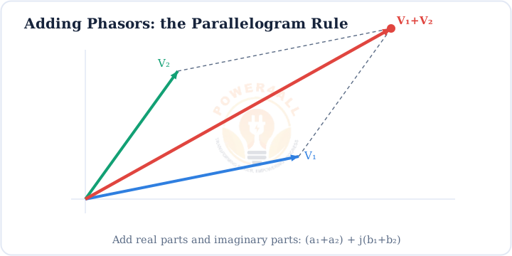
V1 + V2 = (a1+a2) + j(b1+b2)
Resolve each phasor into rectangular components, then add component-wise
Worked example
Add V₁ = 4∠0° and V₂ = 3∠90°:
In rectangular form V₁ = 4 + j0 and V₂ = 0 + j3, so V₁+V₂ = 4 + j3 = 5∠36.87°.
Phasors in AC Circuits
This is where it all pays off. Represent every voltage, current and impedance as a phasor, and the whole toolbox of DC circuit analysis works on AC.
In the phasor domain, a resistor is R, an inductor is +jXL and a capacitor is −jXC. Impedance combines them as Z = R + jX, and Ohm’s law becomes V = I×Z. A phasor diagram draws the voltages as vectors so you can see the phase relationships at a glance.
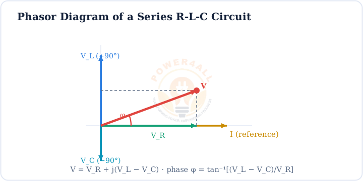
V = VR + j(VL − VC) · φ = tan⁻¹[(VL−VC) / VR]
Total voltage and phase angle of a series RLC circuit from its phasor diagram
Phase angle = power factor angle
The angle φ between voltage and current is the same angle whose cosine is the power factor. Phasors make it fall straight out of the geometry — no calculus required.
Where Phasors & Complex Numbers Are Used
Phasor analysis underpins almost all of AC electrical and electronic engineering.
Circuit analysis
Solve RLC networks, apply Kirchhoff’s laws and Thévenin’s theorem in the phasor domain.
Power & power factor
Real, reactive and apparent power come from phasor voltage × conjugate current.
Filters & resonance
Frequency response and reactance are naturally complex-valued.
Power systems
Three-phase analysis, load flow and fault studies all run on phasors.
Signal processing
The Fourier transform and control theory extend the phasor idea to every frequency.
Communications
Modulation, I/Q signals and antenna phasing are complex-number mathematics.
Practise with the Complex Number & Phasor Calculator and the Impedance Calculator.
Key Terms at a Glance
The essential phasor and complex-number vocabulary students and engineers search for.
Phasor
Rotating vector for a sinusoid: magnitude & phase.
j operator
j = √−1; rotates 90°.
Argand diagram
The complex plane (real & imaginary axes).
Rectangular form
a + jb — real + imaginary.
Polar form
r∠θ — magnitude & angle.
Modulus & argument
|Z| = r, arg Z = θ.
Conjugate
Z* = a − jb; flips the angle.
Euler’s formula
ejθ = cosθ + j sinθ.
Frequently Asked Questions
Quick, expert answers to the questions people ask most about phasors and complex numbers.
What is a phasor in simple words?
A phasor is a little arrow that stands for an AC signal. Its length is the size of the signal (amplitude or RMS) and its angle is the phase — when the signal peaks compared to a reference. Because every signal spins at the same frequency, keeping just length and angle is enough to do the maths.
Why do engineers use j instead of i?
In electrical work the letter i already means instantaneous current, so using it for the imaginary unit would be confusing. Engineers write j = √−1 instead. Mathematically i and j are identical.
What is the difference between rectangular and polar form?
Rectangular form a + jb gives the real and imaginary parts — ideal for adding and subtracting. Polar form r∠θ gives magnitude and angle — ideal for multiplying and dividing. They describe the same point on the complex plane.
How do you convert rectangular to polar form?
For a + jb: the magnitude is r = √(a² + b²) and the angle is θ = tan⁻¹(b/a), adjusted for the quadrant. To reverse it, a = r cosθ and b = r sinθ.
How do you add and multiply phasors?
Add in rectangular form — add the real parts and the imaginary parts. Multiply in polar form — multiply the magnitudes and add the angles. Divide by dividing magnitudes and subtracting angles.
Why are complex numbers used in AC circuits?
They carry magnitude and phase in one quantity, so impedance becomes Z = R + jX and Ohm’s law becomes V = IZ. This turns the differential equations of AC circuits into ordinary algebra.
What does multiplying by j do to a phasor?
It rotates the phasor 90° anticlockwise without changing its length. That is why an inductor’s voltage (+jXL) leads and a capacitor’s (−jXC) lags.
What is Euler’s formula?
ejθ = cosθ + j sinθ. It connects the exponential form r ejθ with the trigonometric form and is the mathematical foundation of the phasor. A rotating sinusoid is r ej(ωt+φ).
Conclusion & Key Takeaways
Phasors turn spinning sinusoids into still vectors, and complex numbers give us the algebra to work with them. Together they make AC analysis simple.
Phasor = rotating vector
Magnitude & phase of a sinusoid.
j = √−1
A “rotate 90°” operator.
a + jb = r∠θ
Two forms, one number.
Add rect, multiply polar
Choose the easy form.
Z = R + jX
Ohm’s law becomes algebra.
Phase angle φ
Falls out of the phasor diagram.